Vehicular lamp unit

a technology of a lamp unit and a lamp body, which is applied in the direction of lighting and heating apparatus, lighting support devices, light source combinations, etc., can solve the problems of merely reducing the brightness of the light distribution pattern in the former lighting mode, difficulty in sufficiently coping with a need, and prolonged extending sideways brightness

a technology of a lamp unit and a lamp body, which is applied in the direction of lighting and heating apparatus, lighting support devices, light source combinations, etc., can solve the problems of merely reducing the brightness of the light distribution pattern in the former lighting mode, difficulty in sufficiently coping with a need, and prolonged extending sideways brightness

US20070279924A1Active Publication Date: 2007-12-06KOITO MFG CO LTD

Image

  • Vehicular lamp unit
  • Vehicular lamp unit
  • Vehicular lamp unit

Examples


Embodiment Construction

[0059]Hereinafter, exemplary embodiments of the present invention will be explained with reference to drawings

[0060]First, the first exemplary embodiment of the invention will be explained.

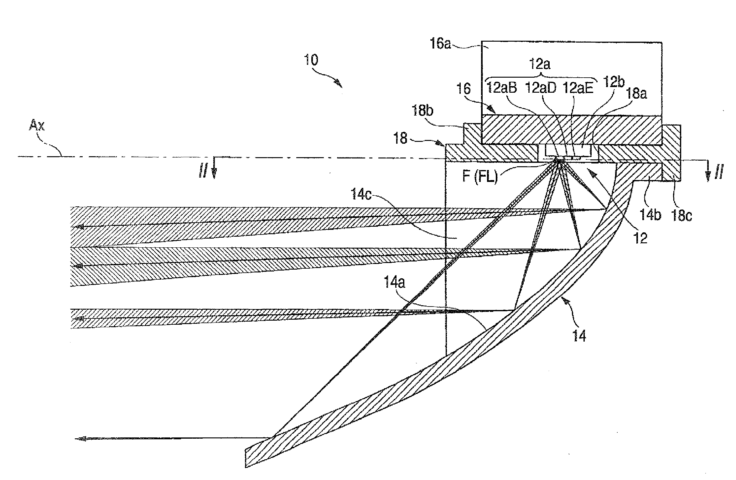
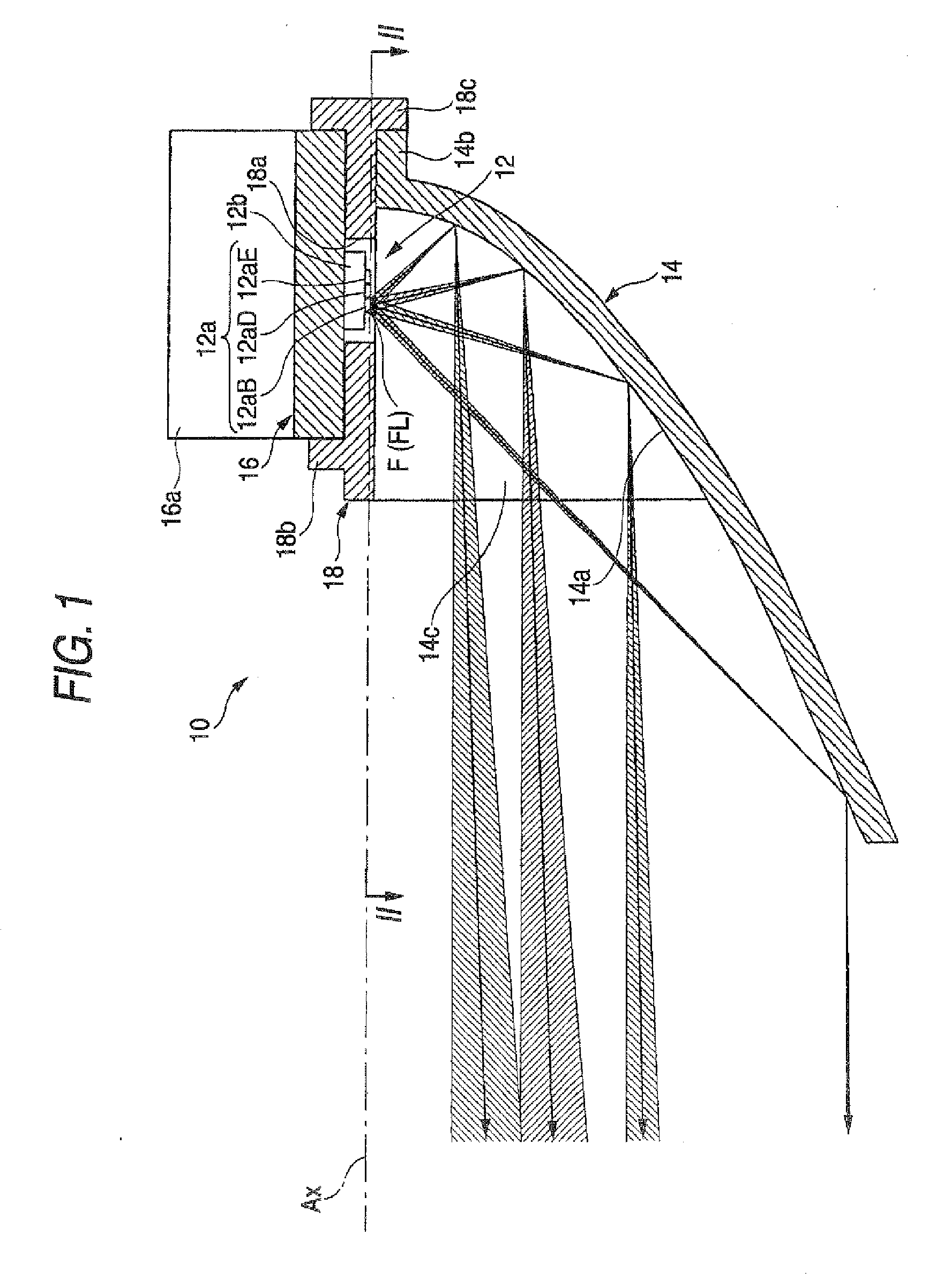
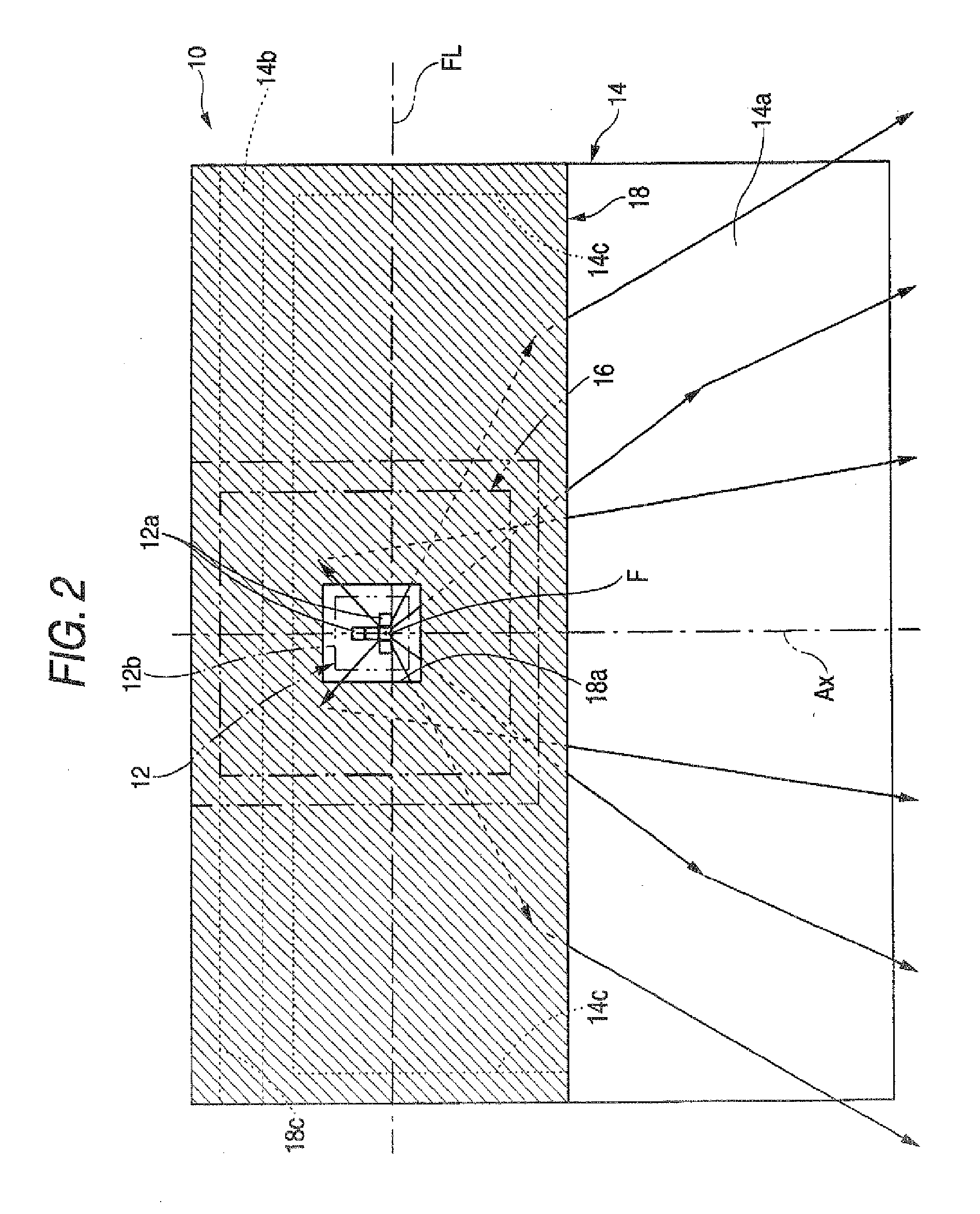
[0061]FIG. 1 is a side sectional view of a vehicular lamp unit 10 according to the first exemplary embodiment. FIG. 2 is a sectional diagram cut along a line II-II in FIG. 1.

[0062]As shown in these figures, the vehicular lamp unit 10 according to the embodiment is configured to include a light emitting element 12 which is disposed on an optical axis Ax extending in the front and rear directions of the lamp unit so as to be directed downward and a reflector 14 which is disposed on the lower side of the light emitting element 12 so as to reflect light emitted from the light emitting element 12 in the forward direction.

[0063]The vehicular lamp unit 10 is incorporated within a not-shown lamp body and used as a part of a vehicular head lamp in a state that the optical axis Ax is disposed so as to exten...


PUM


Abstract

The reflection surface of a reflector is formed by a parabolic cylindrical plane extending in the horizontal direction orthogonal to an optical axis. A light emitting element is configured to have five light emitting chips arranged in a T-shape and these light emitting chips are lighted in two lighting modes. In the first lighting mode, a special light emitting chip and a pair of the left and right side special light emitting chips which front end edges are aligned on the focal line of the parabolic cylindrical plane are lighted simultaneously, whereby a light distribution pattern having a narrow vertical width and a prolong shape is formed. In the second lighting mode, a special light emitting chip located at the center portion and two general light emitting chips disposed in series on the backward side thereof are lighted simultaneously, whereby a light distribution pattern having a large vertical width and a prolong shape is formed.

Description

[0001]This application claims priority from Japanese Patent Application No. 2006-151196, filed May 31, 2006, in the Japanese Patent Office. The priority application is incorporated by reference in its entirety.TECHNICAL FIELD[0002]The present disclosure relates to a vehicular lamp unit having a light emitting element as a light source.RELATED ART[0003]In recent years, light emitting elements such as light emitting diodes have been employed frequently as the light source of the vehicular lamp unit.[0004]For example, Japanese Patent Unexamined Publication No. 2003-31011 and Japanese Patent Unexamined Publication No. 2005-141919 disclose a vehicular lamp unit which is configured in a manner that light irradiated from a plurality of light emitting elements disposed in series in a horizontal direction orthogonal to an optical axis extending in the front and rear direction of the lamp unit is reflected in the forward direction by a reflector having a reflection surface of a parabolic cyli...

Claims


Application Information

Patent Timeline
06 Dec 2007
Publication
US20070279924A1
IPC
F21V1/00; F21W107/10
CPC
F21S48/1159; F21S48/1163; F21Y2113/00; F21S48/1747; F21Y2101/02; F21S48/1317; F21Y2115/10; F21S41/148
Inventors
YAGI, TAKAYUKI