
Light integration rod

a technology light components, which is applied in the direction of instruments, optical waveguide light guides, hollow light guides, etc., can solve the problems of deformation and easy cracking of glass substrates 132/b>, so as to enhance the reliability of light integration rods

Inactive Publication Date: 2007-12-06
YOUNG OPTICS
View PDF5 Cites 11 Cited by
  • Summary
  • Abstract
  • Description
  • Claims
  • Application Information

AI Technical Summary

Benefits of technology

The present invention provides a light integration rod for homogenizing a light beam in an optical projection apparatus. The light integration rod includes a first flat plate, a second flat plate, a first folded plate, and a second folded plate. The first and second flat plates are opposite each other, and the first and second folded plates are connected between the first and second flat plates to form a hollow pillar. The bends of the folded plates are designed to resolve a low-reliability problem encountered in conventional art. The light integration rod can be fixed using a fixing component. The invention also provides alternative light integration rods with different configurations. The metallic substrate of the light integration rod can be made of nickel and silicon. The technical effects of the invention include improved homogenization of light beams and reduced low-reliability issues.

Problems solved by technology

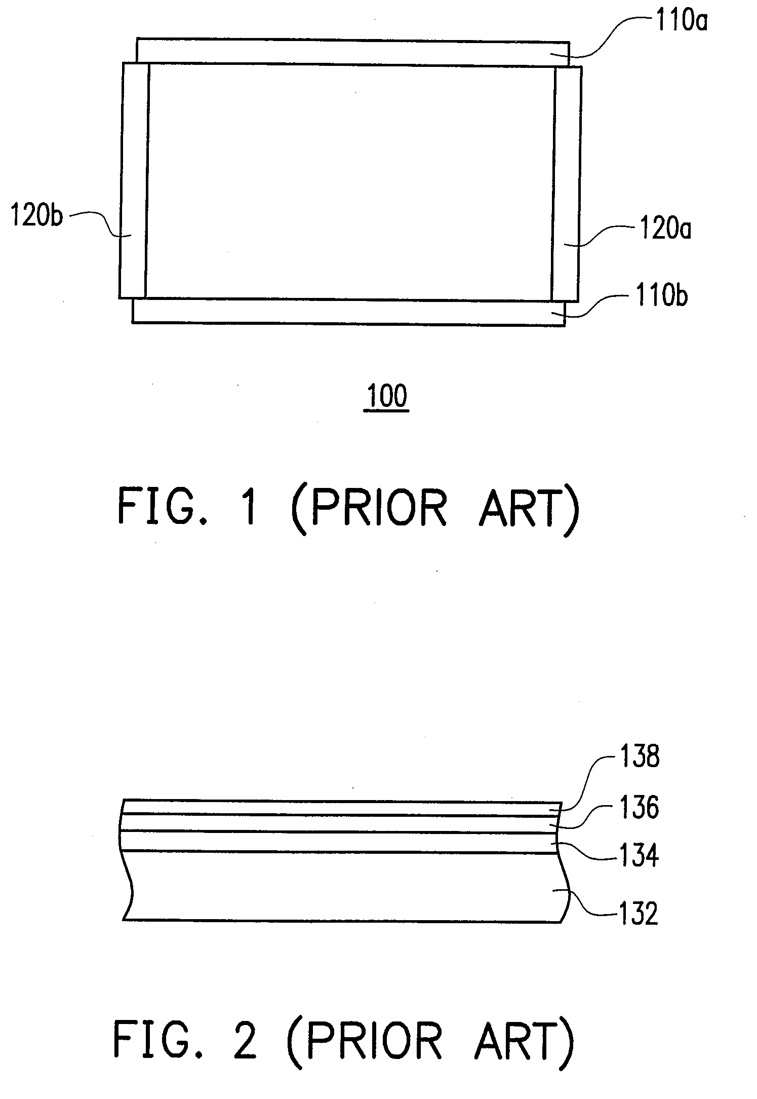
As a result, the glass substrate 132 may easily crack due to pressure.
Furthermore, the glue used for holding the flat plates may degrade when being subject to heat which in turn may lead to deformation of the light integration rod 100.
Ultimately, the uniformity of the light beam output from the light integration rod 100 is adversely influenced.
Consequently, the conventional light integration rod 100 has a low reliability.

Method used


Image

  • Light integration rod
  • Light integration rod
  • Light integration rod

Examples


first embodiment

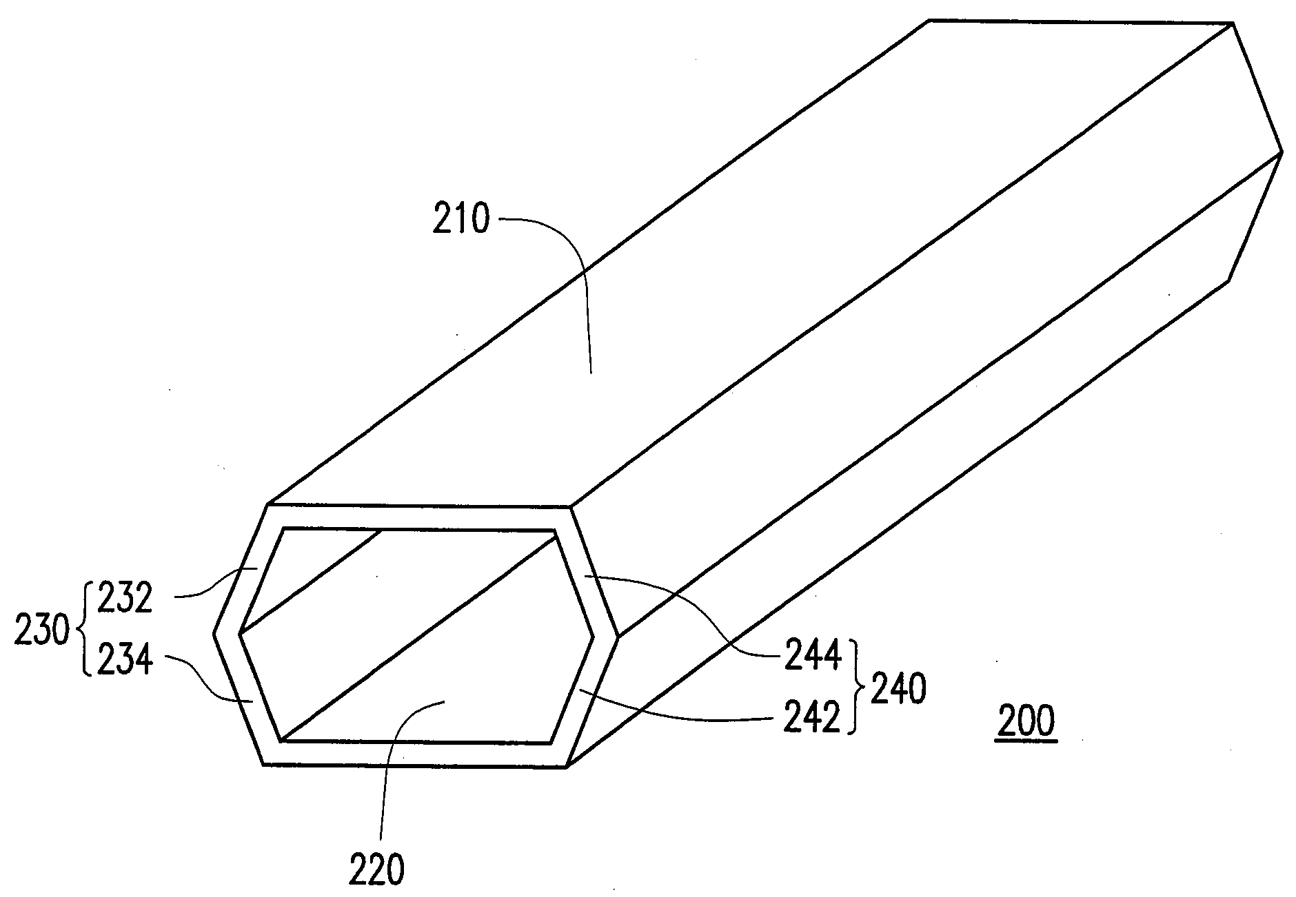
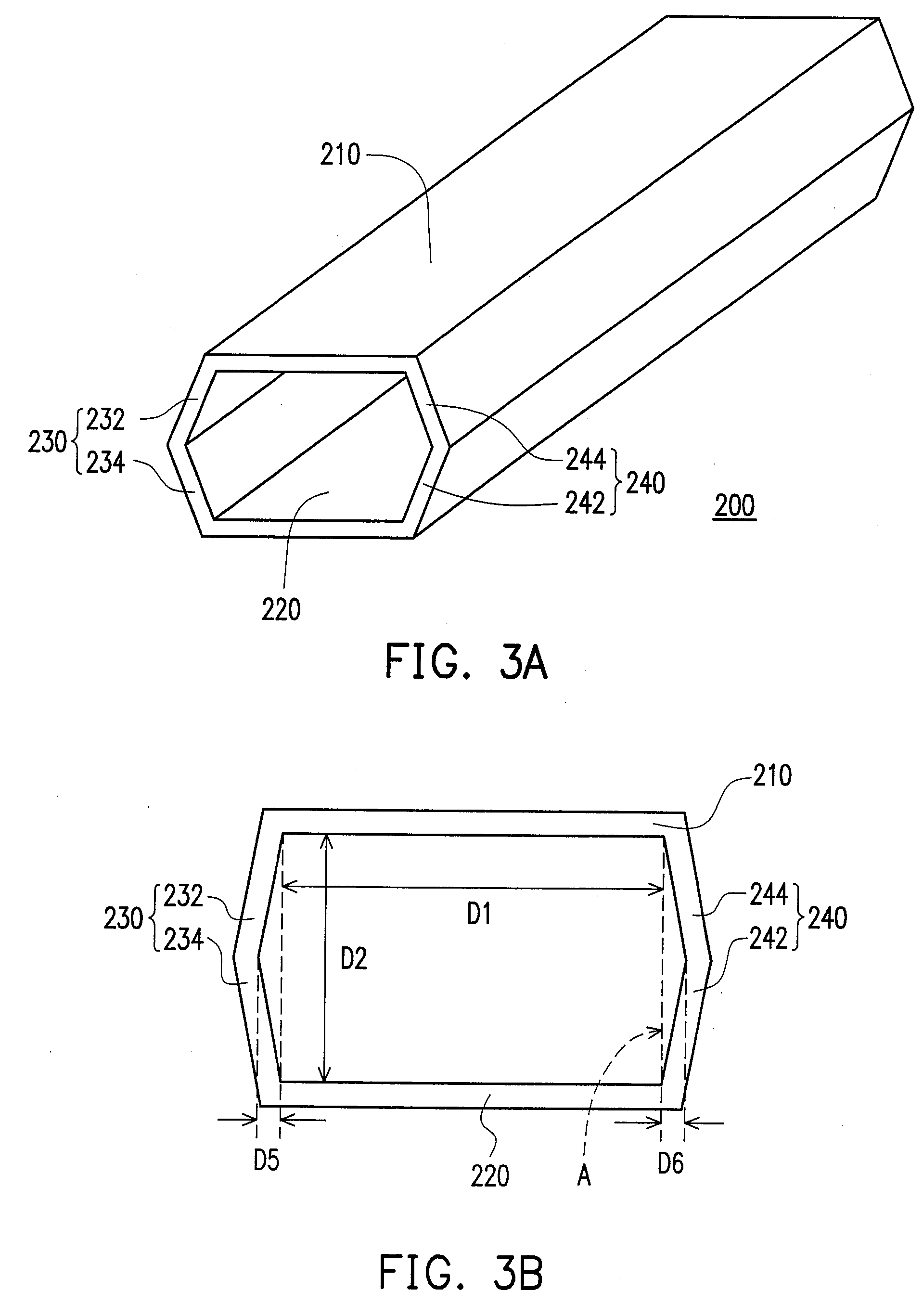
[0039]As shown in FIGS. 3A and 3B, a light integration rod 200 in the present embodiment is suitable for homogenizing a light beam from a light source in an optical projection apparatus (not shown). The light integration rod 200 includes a first flat plate 210, a second flat plate 220, a first folded plate 230 and a second folded plate 240. The first flat plate 210 is opposite to the second flat plate 220, and a shape of the first flat plate 210 is identical to a shape of the second flat plate 220. Similarly, the first folded plate 230 is opposite to the second folded plate 240. The first folded plate 230 and the second folded plate 240 are respectively connected between the first flat plate 210 and the second flat plate 220 to form a hollow pillar. The first folded plate 230 has a first part 232 and a second part 234, and the second folded plate 240 has a first part 242 and a second part 244. The first part 232 of the first folded plate 230 is connected to one edge of the first fla...

second embodiment

[0049]FIG. 8 is a perspective view of a light integration rod according to a second embodiment of the present invention. FIG. 9 is a schematic cross-sectional view showing a first flat plate, a second flat plate, a third flat plate and a fourth flat plate of the light integration rod according to the second embodiment of the present invention. As shown in FIGS. 8 and 9, a light integration rod 300 in the present embodiment includes a first flat plate 310, a second flat plate 320, a third flat plate 330 and a fourth flat plate 340. The second flat plate 320 is opposite to the first flat plate 310, and a shape of the first flat plate 310 is identical to a shape of the second flat plate 320. A shape of the third flat plate 330 is identical to a shape of the fourth flat plate 340. The third flat plate 310 and the fourth flat plate 330 are connected between the first flat plate 310 and the second flat plate 320 to form a hollow pillar. Each of the first flat plate 310, the second flat pl...


PUM


Abstract

A light integration rod including a first flat Plate, a second flat plate opposite to the first flat plate, a first folded plate and a second folded plate opposite to the first folded plate is provided. The first and the second folded plates are respectively connected between the first and the second flat plates to form a hollow pillar. Each of the first and the second folded plates has a first part and a second part. The first part of the first folded plate is connected to an edge of the first flat plate, and the second part of the first folded plate is connected to an edge of the second flat plate. The first part of the second folded plate is connected to an edge of the second flat plate, and the second part of the second folded plate is connected to an edge of the first flat plate.

Description

CROSS-REFERENCE TO RELATED APPLICATION[0001]This application claims the priority benefit of Taiwan application serial no. 95118963, filed May 29, 2006. All disclosure of the Taiwan application is incorporated herein by reference.BACKGROUND OF THE INVENTION[0002]1. Field of the Invention[0003]The present invention relates to an optical element for an optical projection apparatus, and more particularly, to a light integration rod.[0004]2. Description of Related Art[0005]An optical projection apparatus, such as an optical projector, generally includes an illumination system, an imaging system and a projection lens. The illumination system provides an illuminating light beam, the imaging system converts the illuminating light beam into an image light beam, and the projection lens projects the image light beam on a screen, for example. A light integration rod is normally disposed in the illumination system to homogenize the light beam from the illumination system.[0006]FIG. 1 is a schema...

Claims


Application Information

Patent Timeline
Patent Type & Authority Applications(United States)
IPC IPC(8): G02B6/10
CPCG02B6/4298G02B6/0096
Inventor TSOU, TUNG-HSING
Owner YOUNG OPTICS
Learn More