Large diameter mid-zone air separation cone for expanding IRZ

a technology of air separation cone and large diameter, which is applied in the direction of pulverulent fuel combustion burner, combustion type, combustion chamber, etc., can solve the problems of reducing the efficiency of combustion chamber, so as to increase the size of the irz safely and effectively, increase the nox emission, and increase the pressure drop

Active Publication Date: 2007-12-06
THE BABCOCK & WILCOX CO
View PDF10 Cites 16 Cited by
  • Summary
  • Abstract
  • Description
  • Claims
  • Application Information

AI Technical Summary

Benefits of technology

[0008]It is an object of the present invention to provide a device which safely and effectively increases the size of the IRZ, without damaging flow deflecting devices, causing increased NOx emissions, or raising pressure drop.

Problems solved by technology

High swirl combustion can also intensify the fuel / oxidizer mixing and generate high NOx emissions.
Extension of flow deflecting devices (flame holder or air separation cone) into the furnace could expose those parts to high flame temperatures and cause damage.
Increasing the angle of attack on the flow deflecting devices could restrict the air flow passages, raise the pressure drop, and diminish the swirl effects.

Method used


Image

  • Large diameter mid-zone air separation cone for expanding IRZ
  • Large diameter mid-zone air separation cone for expanding IRZ
  • Large diameter mid-zone air separation cone for expanding IRZ

Examples


Embodiment Construction

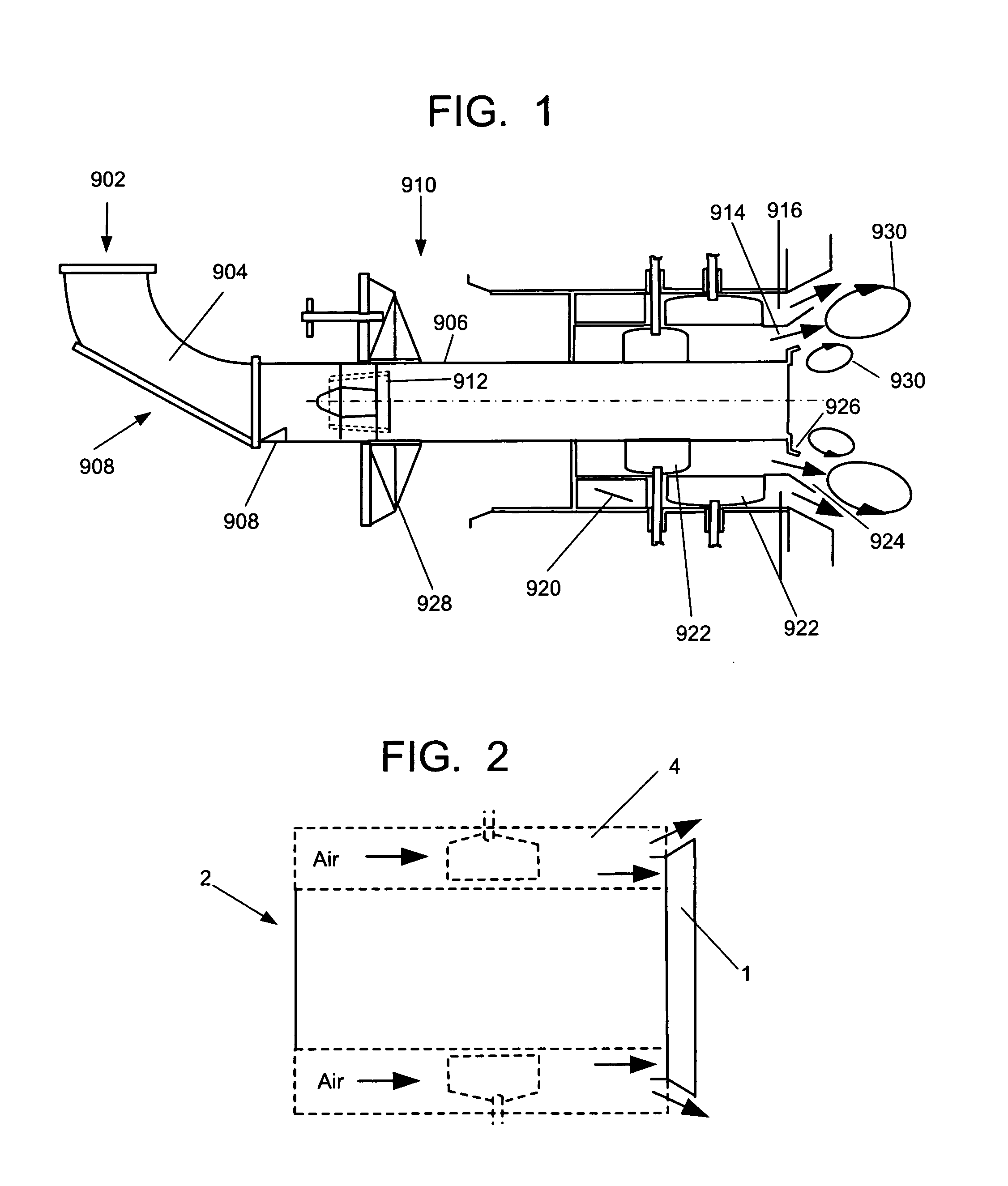
[0021]Referring now to the drawings, in which like reference numerals are used to refer to the same or similar elements, FIG. 2 shows the end of a burner 2 which is adjacent or near a furnace. The end of the burner 2 includes a large diameter mid-adjacent air separation cone 1 with a short cylindrical leading edge that fits in the middle of an outer secondary air zone 4. The device is supported by standoffs (not shown) inside the outer secondary air zone 4 and is not directly connected to any conduits in the burner. It essentially splits the outer air zone 4 secondary air flow into two streams and deflects a portion of the secondary air flow radially outward. Since the radial position of the air separation cone 1 is farther from the burner centerline than the radial position of the conventional air separation cone shown in FIG. 1, it expands the IRZ size and with that, the NOx emissions are minimized.

[0022]The diverging angle of the mid-zone air separation cone can be between 25 to ...


PUM


Abstract

A large diameter mid-zone air separation cone is provided for decreasing NOx during burner operation by expanding the internal recirculation zone (IRZ) at the burner exit. The mid-zone air separation cone has a short cylindrical leading edge that fits in the outer air zone of a burner. The mid-zone air separation cone splits the outer air zone secondary air flow into two equal or unequal streams depending on the position of the air separation cone with respect to the outer air zone, and deflects a portion of the secondary air flow radially outward. Since the radial position of the air separation cone is farther from the burner centerline, the IRZ size is expanded and NOx emissions are minimized.

Description

FIELD AND BACKGROUND OF THE INVENTION [0001]The present invention relates generally to the field of fuel burners and in particular to a new and useful air separation cone for expanding the internal recirculation zone near the exit of one or more air zones surrounding a fuel delivery nozzle.[0002]Low-NOx fossil fuel burners operate on the principle of controlled separation and mixing of fuel and oxidizer for minimizing the oxidation of fuel-bound nitrogen and nitrogen in the air to NOx (i.e., NO+NO2). Use of overfire air in conjunction with fuel-rich combustion is referred to as external (or air) staging. Internal staging involves the creation of fuel-rich and fuel-lean combustion zones within the burner flame. With proper design, fuel-air mixing and swirl patterns can be optimized to create a reverse flow region or “internal recirculation zone” (IRZ) near the burner exit for recycling heat and combustion products including NOx from fuel-lean regions into fuel-rich zones to sustain i...

Claims


Application Information

Patent Timeline
Patent Type & Authority Applications(United States)
IPC IPC(8): F23C7/00F23C1/10F23C1/12
CPCF23D2900/01001F23D1/00
Inventor SARV, HAMIDLARUE, ALBERT D.KAHLE, WILLIAM J.SAYRE, ALAN N.ROWLEY, DANIEL R.
Owner THE BABCOCK & WILCOX CO
Why Eureka
Try Eureka