Exhaust aftertreatment system and method for regenerating a particulate filter

a technology of aftertreatment system and particulate filter, which is applied in the direction of exhaust treatment electric control, separation process, machines/engines, etc., can solve the problems of increasing exhaust heat current, achieve higher load demand, increase the heat generation temperature, and increase the effect of exhaust temperatur

Active Publication Date: 2019-12-12
VOLKSWAGEN AG
View PDF3 Cites 2 Cited by
  • Summary
  • Abstract
  • Description
  • Claims
  • Application Information

AI Technical Summary

Benefits of technology

[0023]The method according to the invention has the advantage that the temperature required for regeneration of the particulate filter can be achieved in all operating situations of a motor vehicle even with a particulate filter in a position remote from the engine, in particular with an underbody installation in the motor vehicle. In doing so, there is no additional load on the battery in these operating situations, in which there is usually only a comparatively low output of the generator and thus a low charging current for the battery, so that regeneration of the particulate filter can take place independently of the charge status of the battery.
[0024]In an advantageous improvement on the method, it is provided that an additional load is generated by the generator on detection of the need for regeneration of the particulate filter, so that an operating point of the internal combustion engine is shifted in the direction of a higher engine torque at the same rotational speed, and a higher exhaust temperature is achieved at the same rotational speed. The required output is increased due to the increase in engine load due to the higher load demand for the generator. Therefore, the temperature of the exhaust increases at a constant rotational speed of the internal combustion engine, so that heating of the particulate filter takes place due to the hotter exhaust gas in addition to the electrical heating of the exhaust stream by the heated catalyst. Therefore, the particulate filter can be heated to its regeneration temperature more quickly under otherwise the same operating conditions.
[0025]In a further improvement of the method, it is provided that the internal combustion engine is operated at a stoichiometric or sub-stoichiometric combustion air ratio during the regeneration of the particulate filter, wherein secondary air is injected into the exhaust system downstream from the last three-way catalyst such that a super-stoichiometric exhaust gas with an exhaust gas air ratio of 1.05<λ<1.2 is established at the entrance to the particulate filter. Therefore, emissions of the internal combustion engine can be converted efficiently by the at least one three-way catalyst, so that regeneration of the particulate filter does not result in an increase in emissions and in particular does not result in an increase in NOx emissions due to super-stoichiometric operation of the internal combustion engine to supply the oxygen required for regeneration of the particulate filter.

Problems solved by technology

Due to the additional load, there is a load point shift of the internal combustion engine, which additionally leads to an increase in the exhaust heat current.

Method used


Image

  • Exhaust aftertreatment system and method for regenerating a particulate filter
  • Exhaust aftertreatment system and method for regenerating a particulate filter

Examples


Embodiment Construction

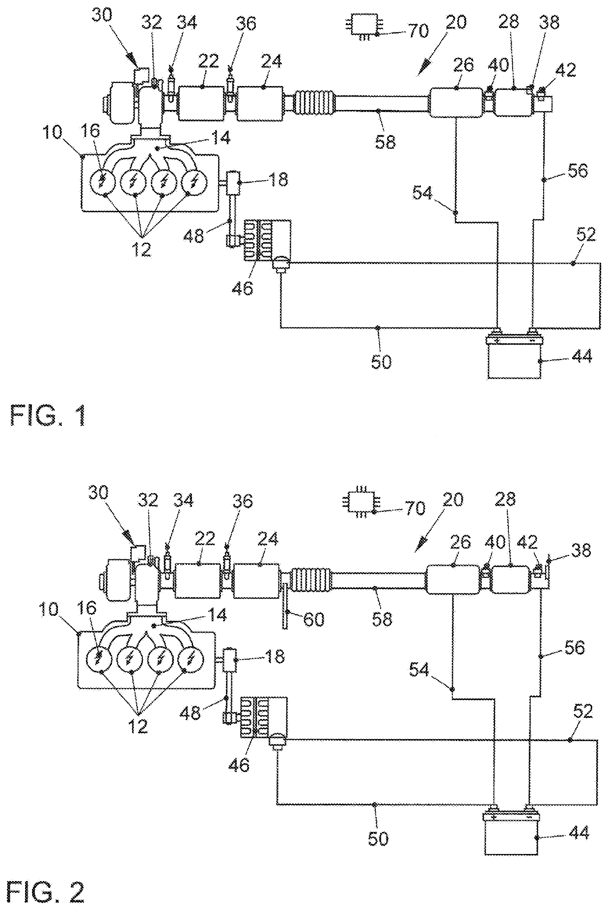
[0032]FIG. 1 shows an internal combustion engine 10 with spark ignition by means of sparkplugs 16. The internal combustion engine has a plurality of combustion chambers 12. The internal combustion engine 10 is connected to an exhaust system 20 at its outlet 14. Furthermore, an output shaft 18 which drives a generator 46 via a drive element 48 is provided on the internal combustion engine. The drive element may be embodied in particular as a belts or a chain. The exhaust system 20 comprises an exhaust channel 58 in which (listed in the direction of flow of the exhaust through the exhaust channel 58) the exhaust channel 58 has a turbine 32 of an exhaust turbocharger 30; downstream from the turbine 32, it has a first three-way catalyst 22 near the motor; and downstream from the first three-way catalyst 22, it has another three-way catalyst 24. Downstream from the second three-way catalyst 24, there is a heated catalyst 26 by means of which an exhaust stream of the internal combustion e...


PUM

PropertyMeasurementUnit
temperaturesaaaaaaaaaa
lengthaaaaaaaaaa
lengthaaaaaaaaaa

Abstract

The invention relates to an exhaust aftertreatment system for an internal combustion engine (10). The exhaust aftertreatment system comprises an exhaust system (20) having at least one three-way catalyst (22, 24) near the engine, wherein a particulate filter (28) is arranged downstream from the three-way catalyst, preferably in an underbody installation in a motor vehicle. A heated catalyst (26), which has at least one heating stage (62, 66, 68) that can be heated by means of an electric heating element (72, 74, 76, 78), is provided upstream from the at least one three-way catalyst (22, 24) and downstream from the particulate filter (28). It is provided that the at least one electrically heatable heating stage (62, 66, 68) is supplied with electric power directly from a generator (46) that is operatively connected to the internal combustion engine (10), so that heating of the heated catalyst (26) takes place essentially independently of the charge status of the vehicle battery (44). The invention also relates to a method for regeneration of a particulate filter (28) in the exhaust system (20) of an internal combustion engine (10) by means of such an exhaust aftertreatment system.

Description

FIELD OF THE INVENTION[0001]The invention relates to an exhaust aftertreatment system for an internal combustion engine as well as a method for regenerating a particulate filter in the exhaust system of a gasoline engine.BACKGROUND OF THE INVENTION[0002]As regulations governing exhaust emissions have steadily become more stringent, the resulting high demands on automobile manufacturers must be met through appropriate exhaust aftertreatment and corresponding measures to reduce crude engine emissions, and with the introduction of the EU6 stage of legislative requirements, the stipulated limits for particle counts for gasoline engines will in many cases necessitate the use of a gasoline particulate filter. Such carbon black particles are formed in particular after a cold start of an internal combustion engine due to incomplete combustion in combination with a sub-stoichiometric combustion air ratio after a cold start as well as the cold cylinder walls and the heterogeneous mixture dist...

Claims


Application Information

Patent Timeline
Patent Type & Authority Applications(United States)
IPC IPC(8): F01N9/00F01N3/023F01N3/035F01N3/10F01N3/20F01N3/30F01N11/00B01D53/94B01D46/00
CPCF01N3/035F01N3/023F01N2900/1402F01N2900/1606F01N2430/06F01N11/007B01D46/0027B01D2255/904B01D53/9454F01N3/2013F01N9/002B01D46/0063F01N2550/04B01D53/9477F01N2900/1602F01N3/30F01N2250/02B01D2279/30F01N2560/025F01N3/101F01N3/027F01N13/009F01N13/0093F01N3/021F01N3/05F01N2240/16Y02A50/20Y02T10/12Y02T10/40B01D46/84
Inventor PAUKNER, STEFANBARON VON CEUMERN-LINDENSTJERNA, FALK-CHRISTIANMANZ, MICHAEL
Owner VOLKSWAGEN AG
Why Eureka
Try Eureka