

Electrical connector
- Summary
- Abstract
- Description
- Claims
- Application Information
AI Technical Summary
Benefits of technology
Problems solved by technology
Method used
Image

Examples
Embodiment Construction
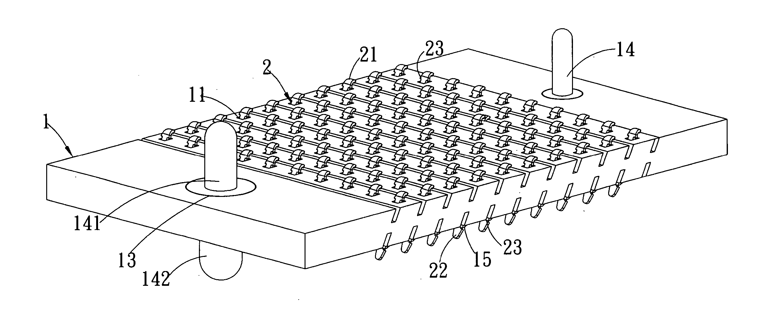
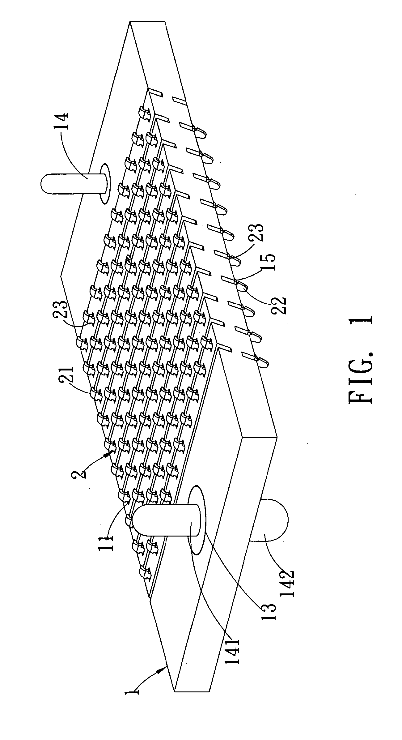
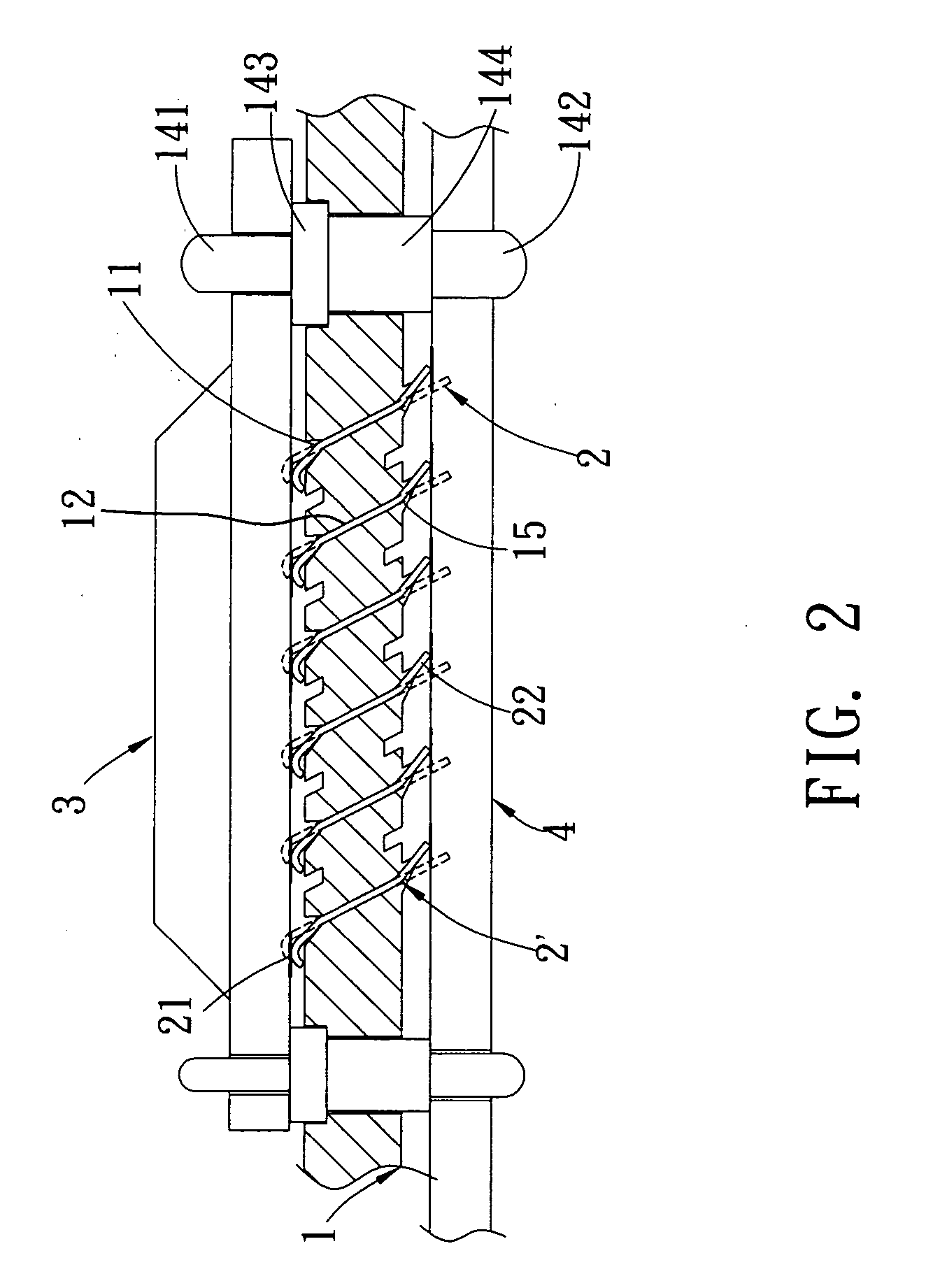
[0017] Referring to FIGS. 1 to 4, the electrical connector according to the present invention is used to connect the electronic devices 3 and 4, comprising an electrically insulating elastic body 1 and a multiple of electrical pieces 2 inclinedly disposed in the electrically insulating elastic body 1. When the electrical connector is compressively contacted with the external electronic device 3, the electrical pieces 2 will undergo rotating displacement; and when the external electronic device 3 retreats from the compressive contact, the electrically insulating elastic body 1 will push the electrical pieces 2 back to their original positions.
[0018] The elastic body 1 is approximately a rectangle provided with a multiple of accommodating grooves 11 to accommodate the electrical pieces 2. The upper walls of the accommodating grooves 11 are inclinedly disposed and an inclined groove 12 is disposed between two neighboring accommodating grooves 11. Both ends of the electrically insulati...
PUM
 Abstract
Description
Claims
Application Information