Eureka AIR delivers breakthrough ideas for toughest innovation challenges, trusted by R&D personnel around the world.

Bicycle hydraulic brake accentuate device

a technology of hydraulic brakes and accentuated devices, which is applied in the direction of cycle brakes, fluid couplings, cycle equipments, etc., can solve the problem that the movement of pads to the rotor requires an undesirable amount of lever arm travel, and achieve the effect of improving the master piston movement respons

Active Publication Date: 2007-12-13
SHIMANO INC
View PDF6 Cites 44 Cited by
  • Summary
  • Abstract
  • Description
  • Claims
  • Application Information

AI Technical Summary

Benefits of technology

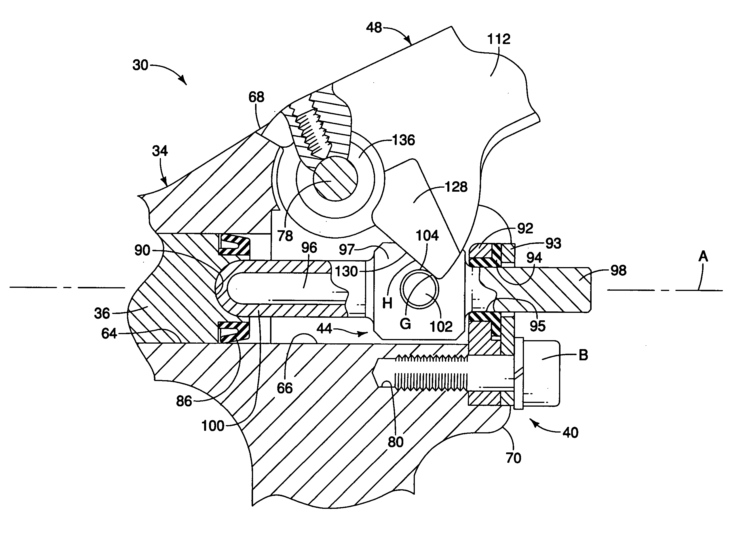
[0011]Another object of the present invention is to provide push rod / roller and lever configuration within a hydraulic brake actuation device that improves braking response.

Problems solved by technology

However, in conventional hydraulic brake actuation devices, movement of the pads to the rotor requires an undesirable amount of lever arm travel.

Method used


Image

  • Bicycle hydraulic brake accentuate device
  • Bicycle hydraulic brake accentuate device
  • Bicycle hydraulic brake accentuate device

Examples


second embodiment

[0063]Referring now to FIGS. 11-17, a hydraulic brake actuation device 230 of a hydraulic braking system in accordance with a second embodiment will now be explained. In view of the similarity between the first and second embodiments, the parts of the second embodiment that are identical to the parts of the first embodiment will be given the same reference numerals as the parts of the first embodiment. Moreover, the descriptions of the parts of the second embodiment that are identical to the parts of the first embodiment may be omitted for the sake of brevity.

[0064]As shown in FIG. 11, the hydraulic brake actuation device 230 has many features identical to the first embodiment. For instance, the hydraulic brake actuation device 230 includes the piston 36 but does not include the movement restricting portion 40 of the first embodiment. The hydraulic brake actuation device 230 does include a hydraulic master cylinder housing 234, a push rod 244 and a lever assembly 248 that include mo...

third embodiment

[0073]Referring now to FIG. 18, a hydraulic brake actuation device 430 of a hydraulic braking system in accordance with a third embodiment will now be explained. In view of the similarity between the first and third embodiments, the parts of the third embodiment that are identical to the parts of the first embodiment will be given the same reference numerals as the parts of the first embodiment. Moreover, the descriptions of the parts of the third embodiment that are identical to the parts of the first embodiment may be omitted for the sake of brevity.

[0074]The hydraulic brake actuation device 430 is identical to the hydraulic brake actuation device 30 of the first embodiment except that the block member 112 has been replaced with a block member 435 and the push rod 44 has been replaced with a push rod 440. The block member 435 includes only a single cam surface area 445. The push rod 440 includes a cam surface contacting portion 445 that includes first and second support walls 450 ...


PUM


Abstract

A bicycle hydraulic brake actuation device includes a hydraulic master cylinder housing having a bore and a push rod guide surface, a master piston and a radial seal received in the bore, a push rod and a lever. The push rod is supported by the push rod guide surface for sliding movement within the hydraulic master cylinder housing. The push rod is configured to move the master piston and the radial seal from a neutral position to a braking position. The lever is pivotally attached to the housing for pivotal movement between an at rest position and a brake actuation position. The lever is also configured and arranged to move the push rod and the master piston from the neutral position toward the braking position as the lever is pivoted between the at rest position and the brake actuation position.

Description

BACKGROUND OF THE INVENTION[0001]1. Field of the Invention[0002]This invention generally relates to bicycle hydraulic brake actuation device. More specifically, the present invention relates to bicycle hydraulic brake actuation device that provides improved braking characteristics in a braking system.[0003]2. Background Information[0004]Bicycling is becoming an increasingly more popular form of recreation as well as a means of transportation. Moreover, bicycling has become a very popular competitive sport for both amateurs and professionals. Whether the bicycle is used for recreation, transportation or competition, the bicycle industry is constantly improving the various components of the bicycle. One system that has been extensively redesigned is the hydraulic brake system.[0005]The bicycle hydraulic brake system typically includes the hydraulic brake actuation device, a rotor attached to one of the bicycle wheels and a caliper adjacent to the rotor with brake pads that selectively...

Claims


Application Information

Patent Timeline
IPC IPC(8): F15B7/08
CPCB60T7/102B62L3/023B60T11/16
Inventor TETSUKA, TOSHIOKARIYAMA, OSAMU
Owner SHIMANO INC
Why Eureka
Eureka Blog
Learn More