Hydraulic braking device of maglev train and maglev train

A magnetic levitation train and hydraulic braking technology, applied in the field of rail transit, can solve the problems of hysteresis and slow braking response speed, and achieve the effect of increasing the speed and reducing the amount of hydraulic oil.

Active Publication Date: 2019-08-27
CRRC TANGSHAN CO LTD
View PDF10 Cites 0 Cited by
  • Summary
  • Abstract
  • Description
  • Claims
  • Application Information

AI Technical Summary

Problems solved by technology

The structure of the maglev vehicle is completely different from the above vehicles. When designing the hydraulic brake system, it is necessary to arrange a long hydraulic pipeline. Compared with the above vehicles, the braking response speed is slower and has a certain hysteresis.

Method used


Image

  • Hydraulic braking device of maglev train and maglev train
  • Hydraulic braking device of maglev train and maglev train
  • Hydraulic braking device of maglev train and maglev train

Examples


Embodiment Construction

[0049] In order to make the purpose, technical solutions and advantages of the embodiments of the present invention clearer, the technical solutions in the embodiments of the present invention will be clearly and completely described below in conjunction with the drawings in the embodiments of the present invention. Obviously, the described embodiments It is a part of embodiments of the present invention, but not all embodiments. Based on the embodiments of the present invention, all other embodiments obtained by persons of ordinary skill in the art without creative efforts fall within the protection scope of the present invention.

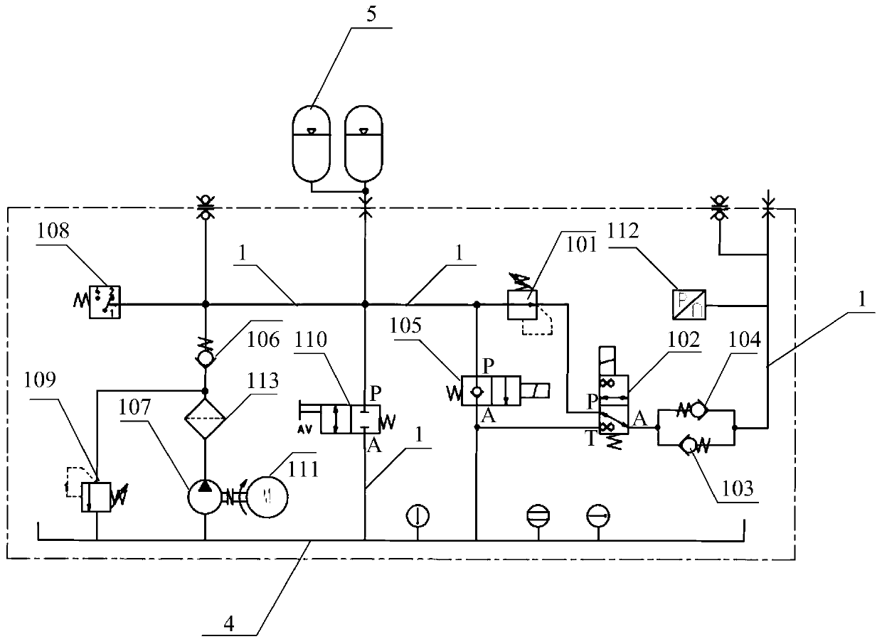
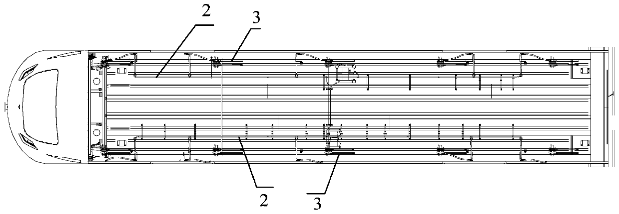
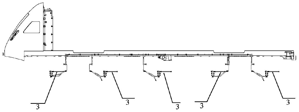
[0050] figure 1 Schematic diagram of the structure of the hydraulic braking device of the magnetic levitation train provided by the present invention; figure 2 Brake pipeline layout of the hydraulic brake device provided by the present invention Figure 1 , image 3 Brake pipeline layout of the hydraulic brake device provided by the present in...


PUM


Abstract

The invention provides a magnetically levitated train and a hydraulic brake device thereof. The hydraulic brake device of the magnetically levitated train comprises a main pipeline, a brake pipeline and a reducing valve, a two-position three-way electromagnetic valve, a first one-way valve and a second one-way valve which are arranged on the main pipeline. An inlet of the reducing valve is communicated with an energy accumulator of the magnetically levitated train, an outlet of the reducing valve is communicated with a port P of the two-position three-way electromagnetic valve, a port A of thetwo-position three-way electromagnetic valve is communicated with an inlet of the first one-way valve and an outlet of the second one-way valve separately, and a port T of the two-position three-wayelectromagnetic valve is communicated with a hydraulic oil tank of the magnetically levitated train; an outlet of the first one-way valve and an inlet of the second one-way valve are communicated withhydraulic driving oil cylinders of brake clamps of the magnetically levitated train through the main pipeline and the brake pipeline. According to the magnetically levitated train and the hydraulic brake device thereof, the brake response speed is increased.

Description

technical field [0001] The invention relates to rail transit technology, in particular to a hydraulic braking device for a magnetic levitation train and the magnetic levitation train. Background technique [0002] Hydraulic braking refers to a form of braking that uses liquid as the transmission medium. It has the characteristics of sensitive response, good follow-up, soft braking, energy saving, simple structure and low cost. At present, hydraulic brake devices are widely used in trams, low-floor trains and other trains. [0003] The hydraulic pipelines of the hydraulic braking devices corresponding to trams and low-floor vehicles are mainly arranged on the bogie, and the pipelines are very short, so the braking response speed is very fast. The structure of the maglev vehicle is completely different from that of the above-mentioned vehicles. When designing the hydraulic brake system, a long hydraulic pipeline needs to be arranged, and the braking response speed is slower t...

Claims


Application Information

Patent Timeline
Patent Type & Authority Patents(China)
IPC IPC(8): B61H7/12B60T13/14B60T13/68
Inventor 杜慧杰刘中华李巍梁生武张英余曹科宇吴瑞梅韩东寅张义文张兴旺
Owner CRRC TANGSHAN CO LTD
Why Eureka
Try Eureka