Device for delivering fuel

a technology for delivering devices and fuel, which is applied in the direction of liquid fuel feeders, machines/engines, separation processes, etc., can solve the problems of unsatisfactory long delay, unfilled mixing ducts, and a tendency to expel the jet, so as to achieve better capture and return

Active Publication Date: 2013-11-26
ROBERT BOSCH GMBH
View PDF15 Cites 6 Cited by
  • Summary
  • Abstract
  • Description
  • Claims
  • Application Information

AI Technical Summary

Benefits of technology

[0005]In contrast, the device according to the invention has the advantage that a situation where the column of liquid in the mixing duct is forced out by the propulsion jet of the suction jet pump is avoided by forming an additional volume at the outlet of the mixing duct by an offset widening of the mixing duct. This provides an additional hydrostatic pressure which prevents the mixing duct from being emptied by the propulsion jet. As a result, the starting time of the suction jet pump up to the start of induction is approximately the same for all operating states. Moreover, continuous induction is ensured for all operating states. The widening of the mixing duct in the additional volume, especially a conical widening, allows better capture and return of the jet of the nozzle into the mixing duct.
[0006]It is particularly advantageous if the deflection means is a depression, recess, receptacle or skirt, into which the jet of the nozzle impinges, the jet being guided back into the mixing duct by the deflection means. The depression, recess, receptacle or skirt has an inlet facing the mixing duct, with the inlet of the deflection means extending into the additional volume. This ensures that less liquid is lost from the mixing duct through splashing.

Problems solved by technology

It has been found that, despite the deflection means, the propulsion jet has a tendency to expel the column of liquid in the mixing duct.
As soon as the liquid level in the reservoir pot has fallen below the outlet of the mixing duct, no more fuel can flow into the mixing duct from above, with the result that the mixing duct may be unfilled after the suction jet pump is switched off.
When the suction jet pump is restarted, an unsatisfactorily long delay then occurs before the beginning of induction by the suction jet pump because the volume of the propulsion jet must first fill the mixing duct in order to build up a vacuum and suction power.
The second suction jet pump has an unsatisfactorily long starting time up to the onset of suction power, owing to the lack of a deflection means.

Method used


Image

  • Device for delivering fuel
  • Device for delivering fuel

Examples


Embodiment Construction

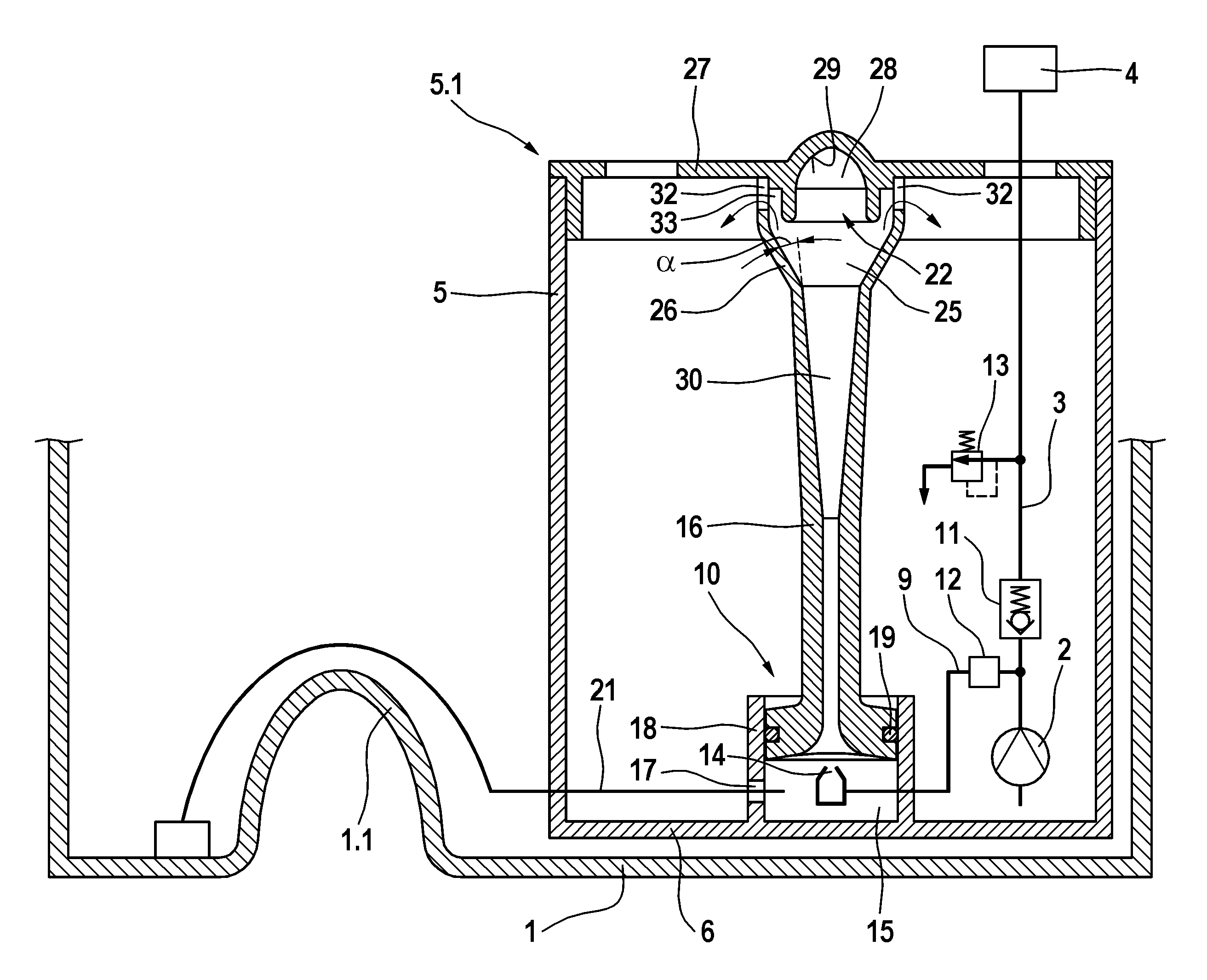
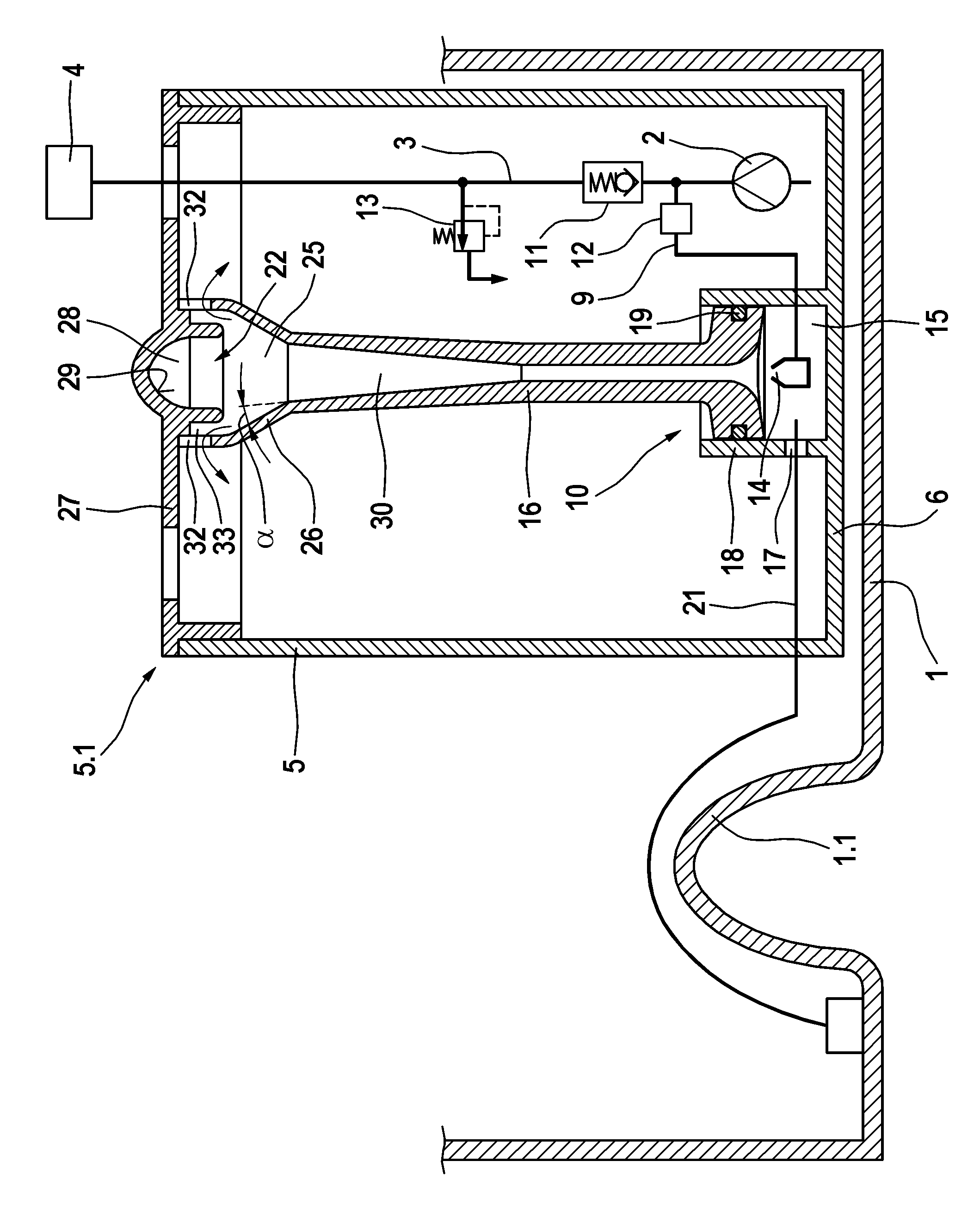
[0008]The drawing shows a section through a device for delivering fuel comprising a suction jet pump according to the invention.

[0009]The device for delivering fuel is arranged in a fuel tank 1 and delivers fuel from the fuel tank 1 at an increased pressure to an internal combustion engine 4 via a pressure line 3 by means of a delivery unit 2, e.g. a fuel pump. The delivery unit 2 is arranged in a reservoir pot 5, which holds sufficient fuel for the delivery unit 2 to ensure that said unit can draw in fuel even when the level of fuel in the fuel tank 1 is low and during acceleration, braking, cornering and / or hill climbing. The reservoir pot 5 has a pot base 6. Branching off from the pressure line 3 of the device is a propulsion line 9, which drives a suction jet pump 10 for active filling of the reservoir pot 5. A pressure control valve 12 can be provided in the pressure line 3 or in the propulsion line 9, said valve allowing fuel to flow out of the pressure line 3 into the propuls...


PUM

PropertyMeasurementUnit
volumeaaaaaaaaaa
hydrostatic pressureaaaaaaaaaa
timeaaaaaaaaaa

Abstract

The present invention includes a device that comprises a suction jet pump, that is arranged in a reservoir pot and has a nozzle and a mixing duct provided downstream the nozzle and arranged perpendicular to a pot base of the reservoir pot. The outlet of the mixing duct has a deflection means, which the jet of the nozzle impinges when the mixing duct is unfilled and has an additional volume formed at the outlet of the mixer by an offset widening of the mixer duct. This additional volume prevents the column of liquid in the mixing duct from being forced out by the propulsion jet of the suction jet pump. Thus the lead time of the suction jet pump is approximately equal in all operating states.

Description

BACKGROUND OF THE INVENTION[0001]The invention starts from a device for delivering fuel.[0002]A device comprising a suction jet pump, which is arranged in a reservoir pot and has a nozzle and a mixing duct provided downstream of the nozzle and arranged perpendicular to a pot base of the reservoir pot, wherein at the outlet of the mixing duct a deflection means is arranged, against which the jet of the nozzle impinges when the mixing duct is substantially unfilled and, in the process, is at least partially guided back into the mixing duct, is already known from DE 42 19 516 A1. It has been found that, despite the deflection means, the propulsion jet has a tendency to expel the column of liquid in the mixing duct. As soon as the liquid level in the reservoir pot has fallen below the outlet of the mixing duct, no more fuel can flow into the mixing duct from above, with the result that the mixing duct may be unfilled after the suction jet pump is switched off. When the suction jet pump ...

Claims


Application Information

Patent Timeline
Patent Type & Authority Patents(United States)
IPC IPC(8): F04F5/00
CPCF02M37/106F02M37/025F02M37/0029F02M37/0088Y10T137/86075
Inventor MARTIN, EUGENKUERMANN, LUDGERGABRIS, MILOSLAV
Owner ROBERT BOSCH GMBH
Why Eureka
Try Eureka