Liquid filter

a liquid filter and filter body technology, applied in the field of liquid filters, can solve the problems of increasing the possibility of leakage problems, the diameter available is not large enough, and it is impossible to form an external thread directly on the cylinder head, so as to increase the diameter available, eliminate the thread nipple

Active Publication Date: 2006-06-22
MANN HUMMEL GMBH
View PDF8 Cites 6 Cited by
  • Summary
  • Abstract
  • Description
  • Claims
  • Application Information

AI Technical Summary

Benefits of technology

[0006] A further object of the invention is to provide a replaceable liquid filter which is less prone to leakage.
[0007] It is also an object of the invention to provide a replaceable liquid filter which and is simple and cost-effective to manufacture.
[0010] According to one advantageous embodiment, the releasable connector comprises a concentric annular collar with an external thread. This concentric annular collar with the external thread can then be screwed directly into the internal thread of the cylinder head and thereby makes a threaded nipple superfluous. Eliminating the threaded nipple also has the advantage of simultaneously increasing the available diameter for the outlet opening for the filtered liquid.
[0013] In accordance with another advantageous embodiment of the invention, a backflow check valve is disposed in the outlet opening in the area of the releasable connector, such that the backflow check valve is disposed axially outside the effective filter element surface. The backflow check valve prevents return flow of liquid and thus prevents the replaceable liquid filter from emptying when the internal combustion engine is stopped. The arrangement of the backflow check valve axially outside the effective filter element surface prevents the largest possible amount of liquid from flowing out of the cartridge filter. Advantageously, the arrangement of the connector extending axially beyond the contour of the liquid filter may be combined with the arrangement of the backflow check valve in precisely this region, thus providing a significant advantage over prior devices.
[0016] It is advantageous if the top plate has a seal at its axially outer end to axially seal the joint between the replaceable liquid filter and the mating part to which it is attached, preferably a cylinder head. Preferably, some kind of a groove is formed in the top plate into which, for example, an O-ring or a cut square gasket is inserted, which creates an axial seal between the replaceable liquid filter and the mating part when the replaceable liquid filter is affixed to the mating part.
[0018] In accordance with yet another embodiment of the invention, a backflow check valve membrane is disposed in the displacement space such that the liquid cannot flow out of the replaceable liquid filter when the filter is removed. The backflow check valve membrane is preferably made of an elastic synthetic resin material (i.e., plastic) or rubber and is open when the internal combustion engine is running because of the pressure of the inflowing liquid. When the internal combustion engine is stopped, the backflow check valve membrane rests over the inlet openings and seals them. This solution is particularly advantageous in replaceable liquid filters that are positioned upright and in these cases prevents the liquid from flowing out of the replaceable liquid filter when the filter is replaced. Because the top plate forms the displacement space, the backflow check valve membrane also prevents the liquid within the displacement space from leaking out. Thus, this backflow check valve membrane in combination with the backflow check valve discussed above, prevents the liquid inside an upright replaceable liquid filter from leaking out during servicing.

Problems solved by technology

It is necessary to use a threaded nipple because of production and material related difficulties that make it impractical to form an external thread directly on the cylinder head.
A drawback of this arrangement is that two pairs of threads must be used, namely, the cylinder head / threaded nipple thread pair on the one hand and the threaded nipple / oil cartridge filter thread pair on the other.
This increases the possibility of leakage problems and also has drawbacks with regard to the diameter available for the outlet in the threaded interior.
Another drawback is the relatively high cost of the threaded nipple.

Method used


Image

  • Liquid filter
  • Liquid filter
  • Liquid filter

Examples


Embodiment Construction

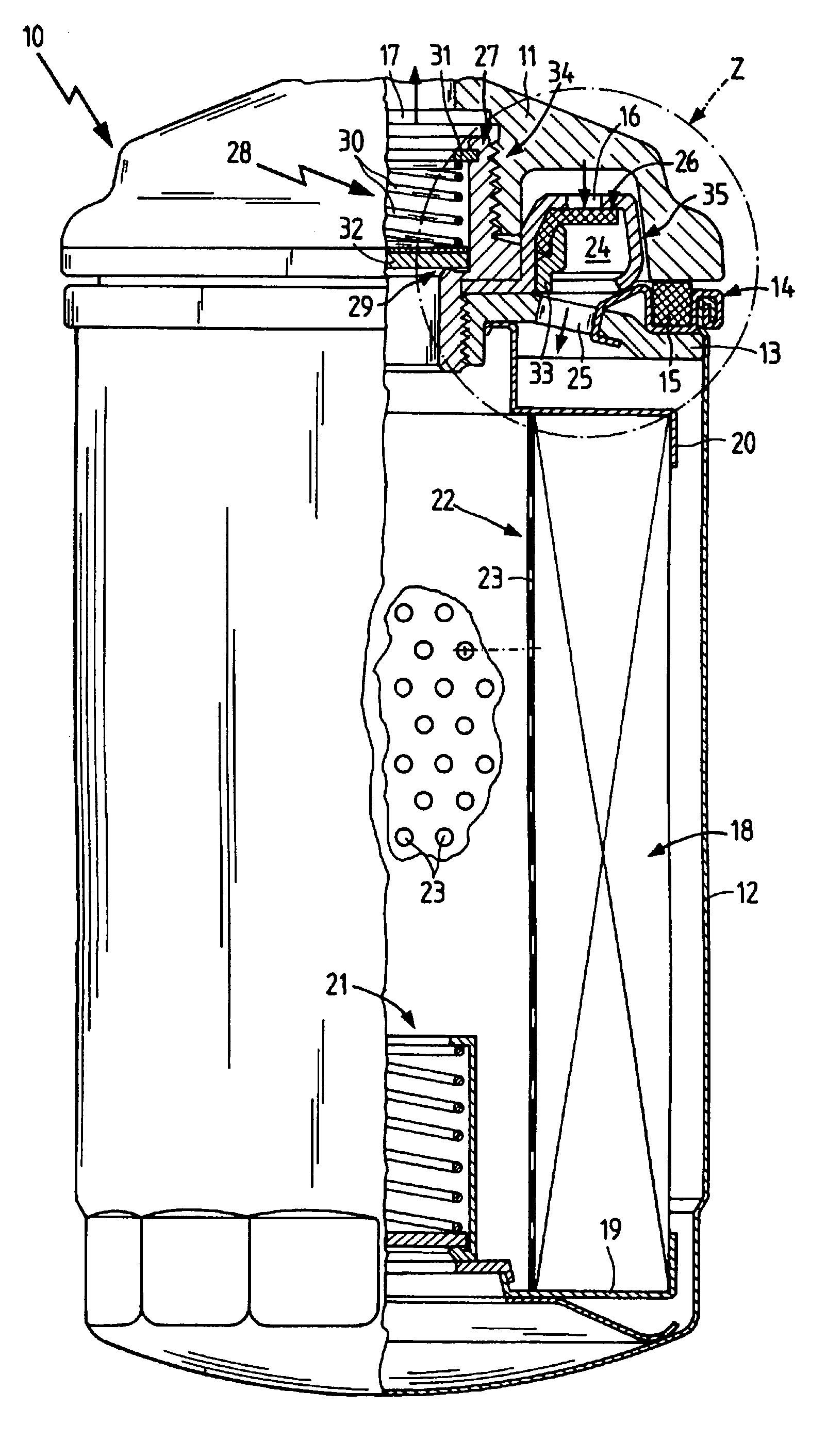
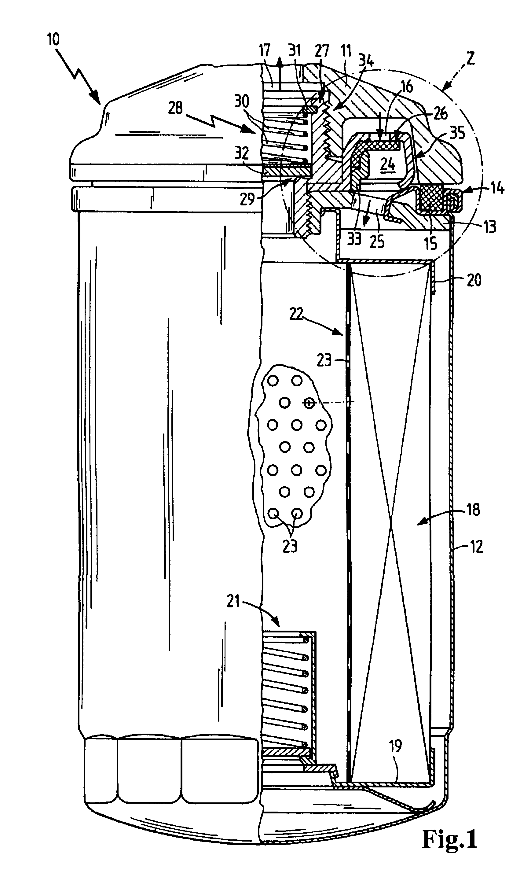
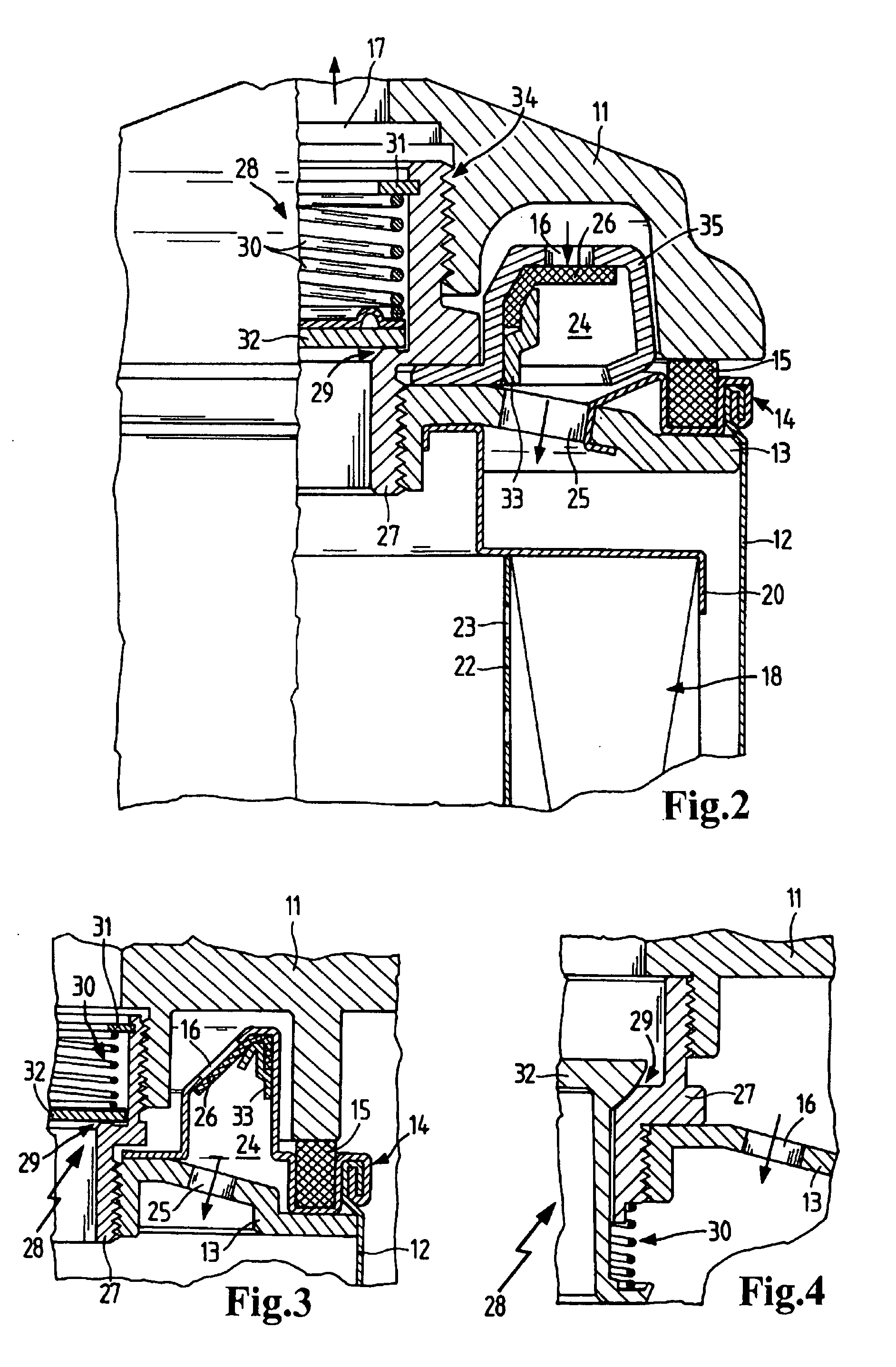
[0024]FIG. 1 shows a replaceable liquid filter 10, which is mounted to a flange on a cylinder head 11. The replaceable liquid filter 10 comprises a cup-shaped housing 12 which is preferably made of metal but may also be made of synthetic resin material, i.e., plastic. In the area of the connection between the cylinder head 11 and the replaceable liquid filter 10, the replaceable liquid filter 10 has a cover plate 13, which is held in place by a top plate 14. The cup-shaped housing 12 is connected to the top plate 14 via a crimped edge, and the cover plate 13 is connected to the top plate 14 by some type of liquid-tight, form-fitting or interlocking connection. To seal the joint between the replaceable liquid filter 10 and the cylinder head 11, a square gasket 15 is disposed in a groove formed in the top plate 14. This square gasket 15 axially seals the replaceable liquid filter 10 relative to the cylinder head 11.

[0025] The replaceable liquid filter 10 further has an inlet opening ...


PUM

PropertyMeasurementUnit
angleaaaaaaaaaa
areaaaaaaaaaaa
diameteraaaaaaaaaa

Abstract

A replaceable liquid filter, particularly for the lubricating oil of an internal combustion engine, having a substantially cup-shaped housing with a concentrically disposed outlet opening for the filtered liquid and at least one inlet opening for the liquid to be filtered and a filter element sealingly disposed between the inlet opening and the outlet opening. The housing is connected to a top plate, and the top plate is connected to an end plate. A connector for releasably coupling the replaceable liquid filter to a mating part is disposed concentrically in the region of the cover plate, such that the connector extends axially beyond the contour of the replaceable liquid filter.

Description

BACKGROUND OF THE INVENTION [0001] The invention relates to a liquid filter, particularly an oil filter for an internal combustion engine, comprising a housing with a concentrically disposed outlet opening for filtered liquid and at least one inlet opening for the liquid to be filtered, and a filter element sealingly disposed between the inlet opening and the outlet opening. [0002] In the prior art, oil cartridge filters, also referred to as spin-on filters, are frequently used. These replaceable oil filters are preferably screwed directly onto the cylinder head of an internal combustion engine and are thus integrated into the oil circuit of the engine. To this end, an internal thread is provided in the cylinder head of the internal combustion engine into which a threaded nipple is firmly screwed having an external thread extending axially away from the cylinder head. The oil cartridge filter, comprising a cup-shaped housing and an end plate with a thread disposed concentrically the...

Claims


Application Information

Patent Timeline
Patent Type & Authority Applications(United States)
IPC IPC(8): B01D27/08B01D35/30
CPCB01D27/103B01D35/306B01D27/106
Inventor LUKA, HELMUTSCHRECKENBERGER, DIETERLOOS, RAINERKOLCZYK, MARKUS
Owner MANN HUMMEL GMBH
Why Eureka
Try Eureka