Fuel injection system of internal combustion engine, and fuel injection method of the internal combustion engine

Inactive Publication Date: 2007-12-13
NISSAN MOTOR CO LTD
View PDF11 Cites 54 Cited by
  • Summary
  • Abstract
  • Description
  • Claims
  • Application Information

AI Technical Summary

Benefits of technology

[0007]The present invention has been made in consideration for such a problem. It is an object of the present invention to provide a fuel injection system that reduces the energy to be suppli

Problems solved by technology

Therefore, necessary energy in the event of heating the fuel up to a predetermined temperature is large, it is inevitably necessary to supply large electric power to the fuel injection system, and the fuel injection system cannot help but being enlarged as an apparatus.
In addition, in the case of setting the fuel into the supercritical state, the fuel must be heate

Method used


Image

  • Fuel injection system of internal combustion engine, and fuel injection method of the internal combustion engine
  • Fuel injection system of internal combustion engine, and fuel injection method of the internal combustion engine
  • Fuel injection system of internal combustion engine, and fuel injection method of the internal combustion engine

Examples


Example

First Embodiment

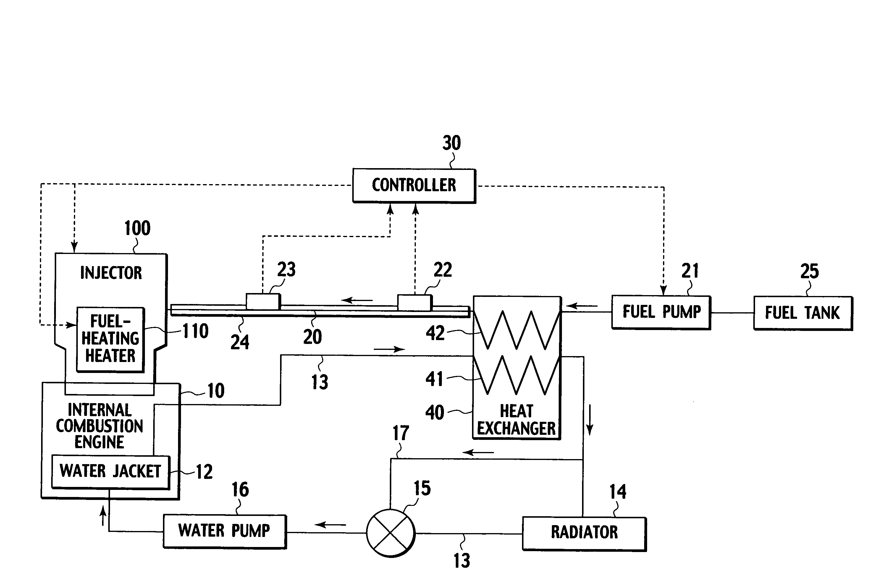
[0027]A description will be made of a first embodiment. FIG. 1 is a schematic view showing an entire configuration of a first embodiment.

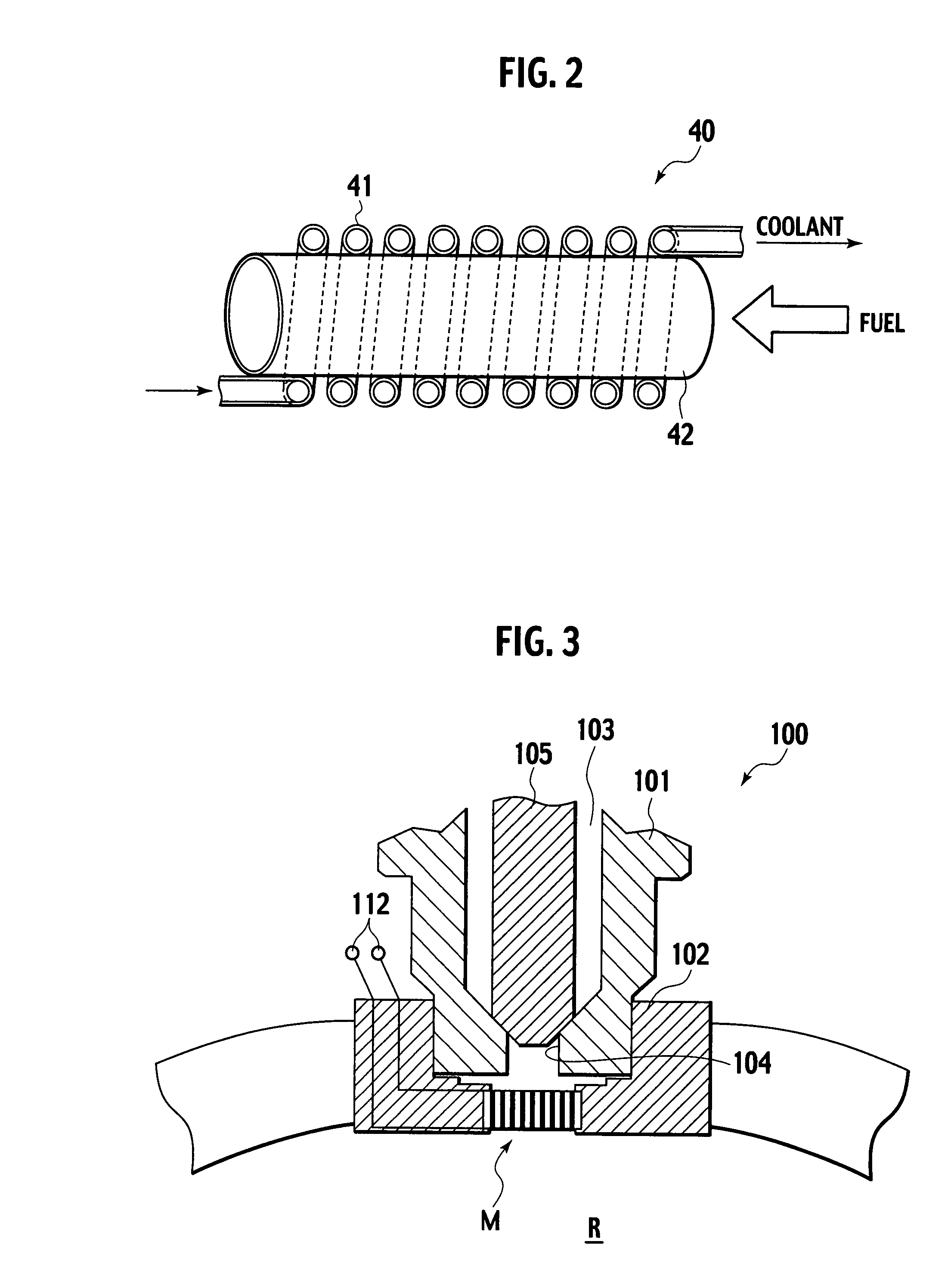
[0028]Onto an internal combustion engine 10, an injector 100 in which a jet orifice is directed to a combustion chamber is attached. Fuel is supplied to the injector 100 through a fuel pipe 20.

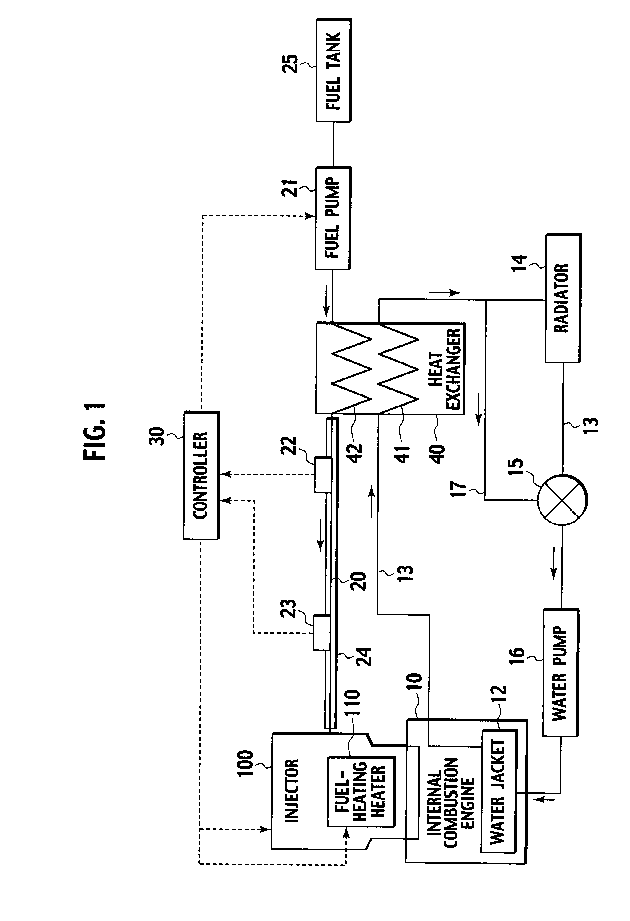
[0029]A heat exchanger 40 is provided on the way of the fuel pipe 20. Further, on a fuel tank 25 side of the fuel pipe 20 from the heat exchanger 40, a fuel pump 21 that pressurizes the fuel and feeds the fuel with pressure is disposed. Arrows added to the fuel pipe 20 indicate a flowing direction of the fuel. Moreover, to the fuel pipe 20, there are added a pressure sensor 22 and a temperature sensor 23 on a downstream side of the heat exchanger 40, that is, on the injector 100 side. The pressure sensor 22 and the temperature sensor 23 detect a pressure and temperature of the fuel supplied to the injector 100.

[0030]The pressure sensor 22 and ...

Example

Second Embodiment

[0055]Next, a description will be made of a second embodiment. Note that, with regard to a configuration of this embodiment, the same reference numerals are assigned to similar portions to those of the first embodiment in the drawings, and a duplicate description will be omitted.

[0056]FIG. 9 is a schematic view showing an entire configuration of the second embodiment. In the second embodiment, an outer wall of the internal combustion engine is used as the heat source of the heat exchanger in place of the coolant.

[0057]Onto the internal combustion engine 10, the injector 100 in which the jet orifice is directed to the combustion chamber (not shown) is attached. To the injector 100, the fuel is supplied through the fuel pipe 20. The injector 100 is the same as that in the first embodiment, and in the jet orifice, includes the micro nozzle M as the fuel-heating heater 110 that heats the fuel. On the way of the fuel pipe 20, a heat exchanger 40A formed on the outer wall...

Example

Third Embodiment

[0066]Next, a description will be made of a third embodiment. Note that, with regard to a configuration of this embodiment, the same reference numerals are assigned to similar portions to those of the first embodiment in the drawings, and a duplicate description will be omitted.

[0067]FIG. 11 is a schematic view showing an entire configuration of the third embodiment. In the third embodiment, the coolant is used as the heat source of the heat exchanger in a similar way to the first embodiment.

[0068]On the way of the fuel pipe 20, a heat exchanger 40 that is similar to the one in the first embodiment is provided, and further, on the fuel tank side of the heat exchanger 40, the fuel pump 21 that pressurizes the fuel and feeds the fuel with pressure is disposed. Moreover, to the fuel pipe 20, there are added the pressure sensor 22 and the temperature sensor 23 on the downstream side of the heat exchanger 40, that is, on the injector 100 side. The pressure sensor 22 and t...


PUM


Abstract

A fuel injection system of an internal combustion engine has an injector that injects fuel into an intake system or a combustion chamber of an internal combustion engine, and a pressurizing device that pressurizes the fuel to a predetermined pressure. Further, the system has a first heating device that heats the fuel on an upstream side of the injector, and a second heating device that further heats the fuel heated by the first heating device. The second heating device is provided in the injector. Furthermore, the system has a control device that controls the second heating device to heat up the fuel heated by the first heating device to a predetermined temperature.

Description

BACKGROUND OF THE INVENTION[0001]1. Field of the Invention[0002]The present invention relates to a fuel injection system that heats and pressurizes fuel, and injects the heated and pressurized fuel into a combustion chamber of an internal combustion engine.[0003]2. Description of the Related Art[0004]As a fuel injection system for a vehicle and the like, there is proposed the one using an injector that sets fuel into a high-temperature and high-pressure liquid state or a supercritical state and injects such fuel into a combustion chamber. By the injector described above, the fuel injected into the combustion chamber of the internal combustion engine is actively atomized and vaporized, and good combustion can be thereby realized. As such injector, there is the one disclosed in Japanese Patent Unexamined Publication No. H10-141170.BRIEF SUMMARY OF THE INVENTION[0005]The conventional fuel injection system has a configuration in which the fuel is heated up from the room temperature only...

Claims


Application Information

Patent Timeline
IPC IPC(8): F02M53/06
CPCF01P2060/10F02M31/125F02M53/02F02M53/06Y02T10/126F02M63/0225F28D7/0016F28D7/024F28F3/12F02M61/1853Y02T10/12
Inventor FUKUMOTO, TAKAFUMIKANEKO, HIROYUKIKIRITANI, NORIHIKOYAMAGUCHI, RYUUTAIGARI, YUUICHI
Owner NISSAN MOTOR CO LTD
Why Eureka
Try Eureka