Epoxy secured stop collar for centralizer

Inactive Publication Date: 2007-12-13
FRANKS INT
View PDF5 Cites 43 Cited by
  • Summary
  • Abstract
  • Description
  • Claims
  • Application Information

AI Technical Summary

Benefits of technology

[0012]The centralizer stop collar of the present invention provides improved securing of centralizers at selected locations on casing strings that are made up and run into boreholes. The centralizer stop collar of the present invention is adapted to be received and secured onto the outside of a segment of casing using epoxy adhesive. The centralizer stop collar is designed to form an annular chamber between the interior bore of the sleeve and the external surface of the

Problems solved by technology

Sliding of the centralizers results in some intervals having insufficient stand-off between the casing string and the borehole, with resulting poor cement placement in the annulus and possible well failure.
Centralizers may engage borehole restrictions or irregularities resulting in large forces urging the centralizer off its sets position on the casing string.
Set screws perform poorly where the pipe on which the stop collar is secured is very

Method used


Image

  • Epoxy secured stop collar for centralizer
  • Epoxy secured stop collar for centralizer
  • Epoxy secured stop collar for centralizer

Examples


Embodiment Construction

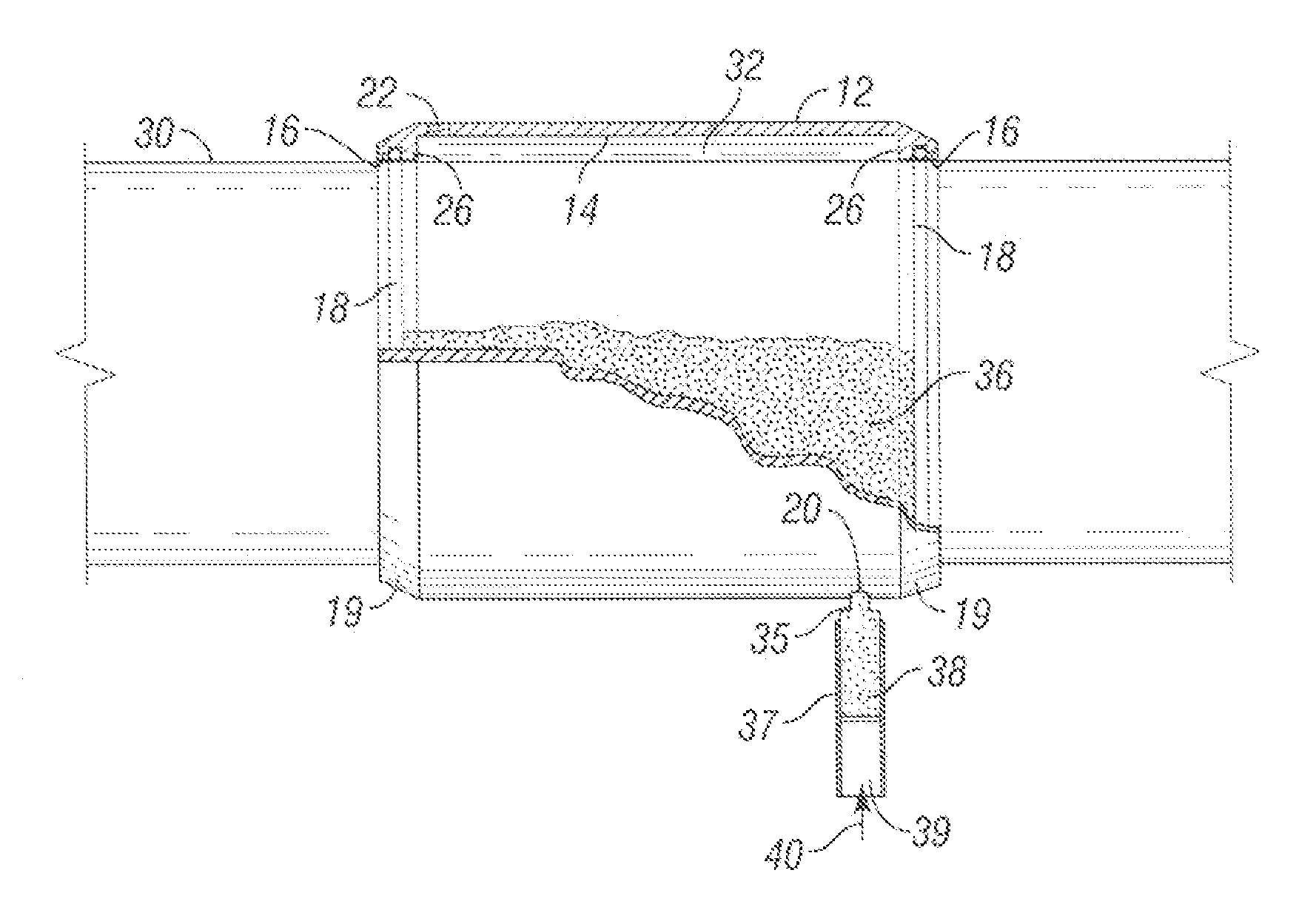
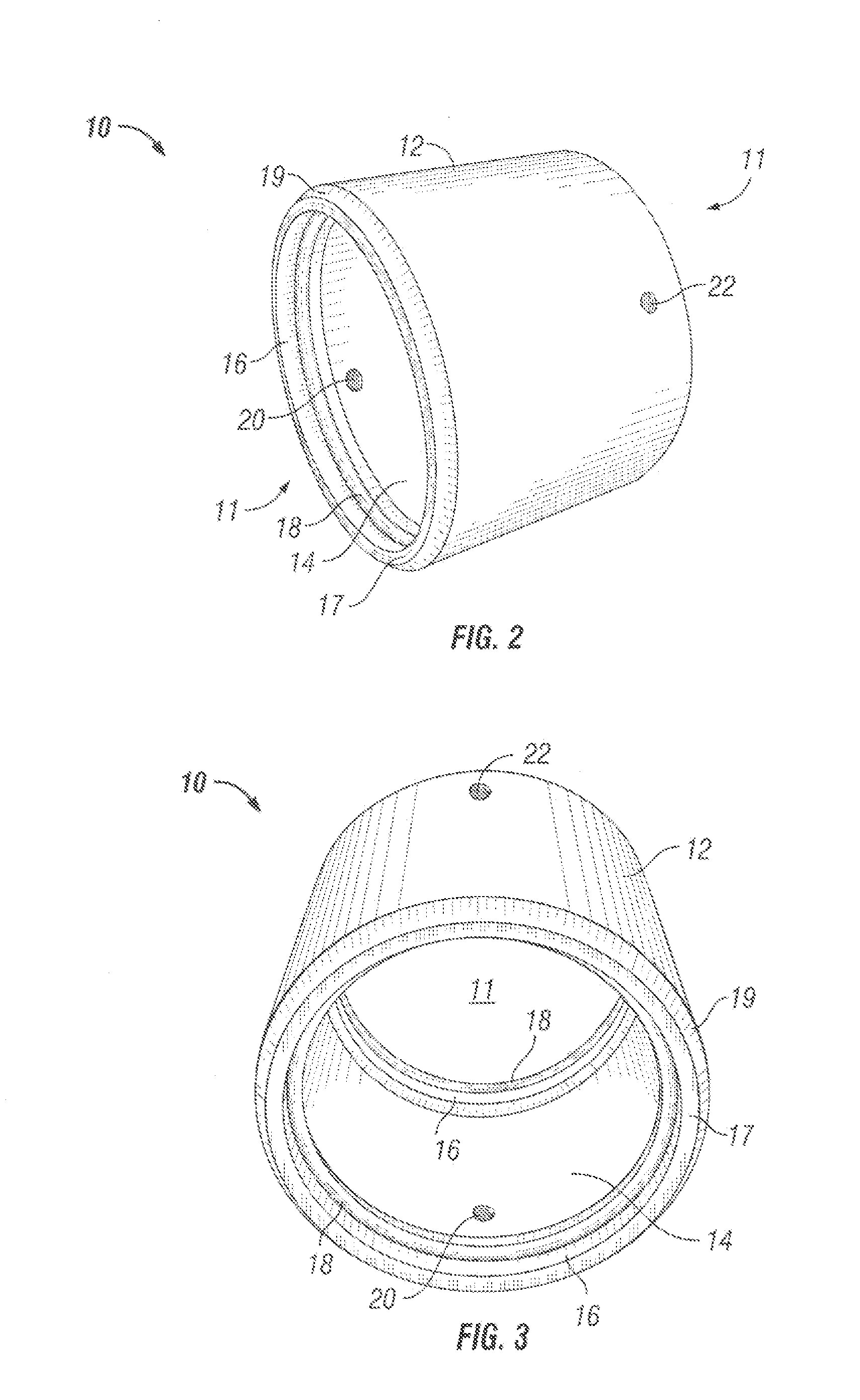
[0019]FIG. 2 is a perspective side view of one embodiment of the centralizer stop collar 10 of the present invention having a center bore 11 for receiving a casing segment, an external wall 12 and an internal wall 14. The openings 16 disposed at the ends of the bore 11 are of a slightly smaller diameter than the interior portion of the bore 11 along the internal wall 14 between the openings 16. This interior portion forms an annular chamber around the casing and within the stop collar 10 between the openings 16 when a casing segment (not shown) is received within the bore 11.

[0020]A circumferential landing 17 is disposed around each opening 16. The landing 17 is generally perpendicular to the axis of the bore 11, and is adapted for abutting contact with a moving collar of a centralizer (not shown). The opening 16 is adapted for receiving and securing an O-ring 18 to form a seal between the opening 16 and the external wall of the casing (not shown) received within the bore 11.

[0021]T...


PUM

PropertyMeasurementUnit
Diameteraaaaaaaaaa
Surface areaaaaaaaaaaa

Abstract

A stop collar for securing a centralizer in place on a large diameter easing segment comprises a collar adapted for forming an annular chamber when received onto a casing segment. The stop collar is adapted for receiving and retaining a liquid gel epoxy adhesive in the annular chamber until the epoxy sets or cures to secure the stop collar in place on the casing.

Description

BACKGROUND[0001]1. Field of the Invention[0002]the present invention is directed to a stop collar for securing a centralizer on a pipe segment that is made up into a pipe string for installation into a drilled earthen borehole. Specifically, the present invention is directed to a sleeve that is adapted for being slidably received on and then secured to a pipe segment with an epoxy adhesive.[0003]2. Description of Related Art[0004]Casing is tubular pipe generally used to line a drilled earthen borehole to prevent collapse and to isolate the penetrated geologic formations. A tubular joint of casing is typically about 36 to 44 feet in length, and has threaded connections at each end to facilitate coupling to adjacent joints of casing to form an elongated casing string. Casing strings are made up as they are run into the borehole. After the desired length is achieved, the casing string is cemented into the borehole in the targeted interval. A predetermined volume of cement slurry is pum...

Claims


Application Information

Patent Timeline
IPC IPC(8): B32B37/00
CPCE21B17/1028E21B37/02E21B17/1078
Inventor BUYTAERT, JEAN
Owner FRANKS INT
Why Eureka
Try Eureka