Integrated contact lens case and replacement time

a contact lens and carrying case technology, applied in the field of replacement of contact lenses, can solve the problems of increased consecutive days of extended lens wear, ulcerative karatitis risk, and ulceration of the cornea,

a contact lens and carrying case technology, applied in the field of replacement of contact lenses, can solve the problems of increased consecutive days of extended lens wear, ulcerative karatitis risk, and ulceration of the cornea,

US20070284263A1Inactive Publication Date: 2007-12-13ANDRE DAVID

Image

  • Integrated contact lens case and replacement time
  • Integrated contact lens case and replacement time
  • Integrated contact lens case and replacement time

Examples


Embodiment Construction

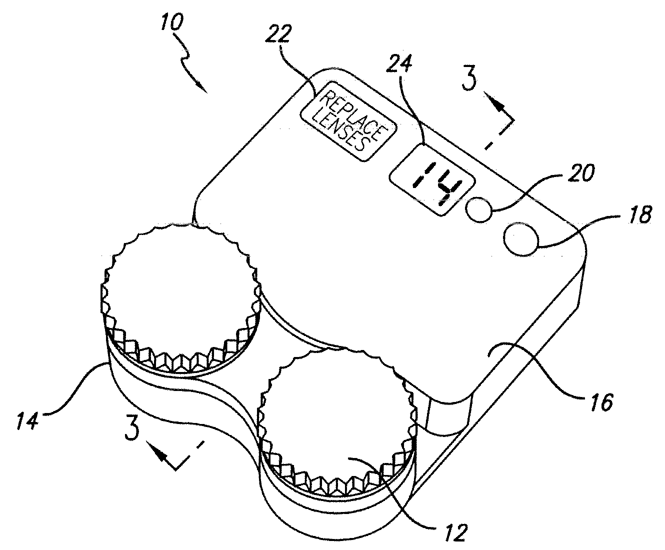
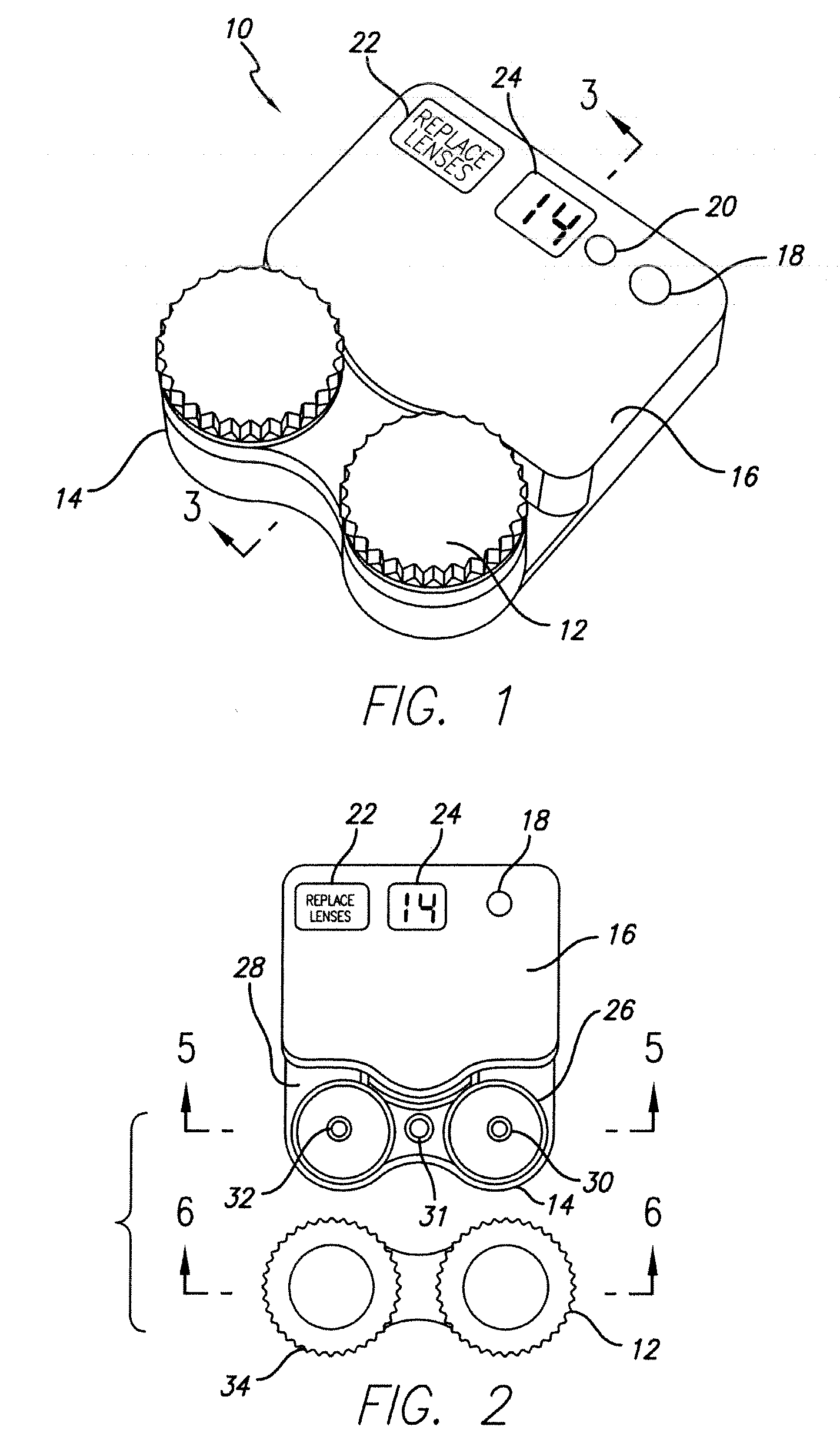
[0015]Referring now to the drawings and more particularly to FIG. 1, there is illustrated an integrated apparatus 10 which includes a contact lens carrying case 12 affixed to a pedestal or mount 14 which is constructed as an integral part of a housing 16 within which the electronic timer apparatus is disposed. The housing includes a button 18 which is utilized to set the timer according to the replacement periodicity designated by the physician or optometrist. For example, if the physician or optometrist has indicated that the lenses should be replaced once every seven days, then the set button 18 would be depressed one time. If, however, the contact lenses were such that they could be worn for a period of two weeks, then the set button would be pressed twice. If, however, the lenses were of the new Silicone Hydrogel or gas permeable lens which could be worn for a period of thirty (30) days, then the set button would be depressed three times.

[0016]Typically, the user would use or de...


PUM


Abstract

An integrated contact lens case and an electronic timer which may be set to a predetermined time such as seven, fourteen or thirty days as the period during which the user may use contact lenses before replacing them. The timer generates an electrical signal upon reaching the predetermined time which signal is applied to an indicator carried by the housing to provide a visual signal to the user that the time for replacing the contact lens has arrived. The contact lens case is removably secured through the housing within which the electronic timer apparatus is disposed by a plurality of complimentary protrusions and recesses.

Description

RELATED APPLICATION[0001]This application is based upon Provisional Application 60 / 812,516, filed Jun. 8, 2006 and hereby claims benefit of the filing date thereof.FIELD OF THE INVENTION[0002]The present invention relates generally to the replacement of contact lenses and more particularly to the combination of a contact lens carrying case which is integrally formed with a timer adapted to indicate to the user when replacement of the contact lens should be accomplished.BACKGROUND OF THE INVENTION[0003]Use of contact lenses is very prevalent among individuals requiring vision correcting lenses. Many of the contact lenses which are utilized are referred to as disposable contacts. Such disposable contact lenses must be replaced on a periodic basis which usually is determined by the type of lens and the prescription which is provided by the physician or optometrist. Many of the disposable contact lenses are approved to be worn without replacement for up to seven days and some for fourte...

Claims


Application Information

Patent Timeline
13 Dec 2007
Publication
US20070284263A1
IPC
A45C11/04
CPC
A45C11/005; A45C15/08; A45C13/001
Inventors
GIARDINA, E. RIC; ANDRAE, DAVID