
Wireless communication terminal apparatus and method of controlling same

a terminal and wireless technology, applied in the direction of burglar alarm mechanical actuation, burglar alarm by hand-held articles removal, instruments, etc., can solve the problems of limited use of elements, fet, and inability to provide a complete solution to the above problems, so as to reduce the cost of facilities and facilitate the adjustment of resonance frequency f0

Inactive Publication Date: 2007-12-13
SONY CORP
View PDF3 Cites 33 Cited by
  • Summary
  • Abstract
  • Description
  • Claims
  • Application Information

AI Technical Summary

Benefits of technology

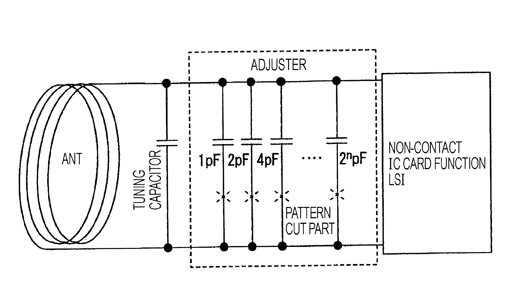
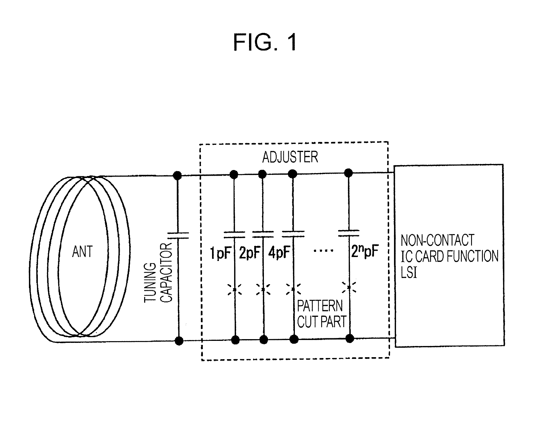
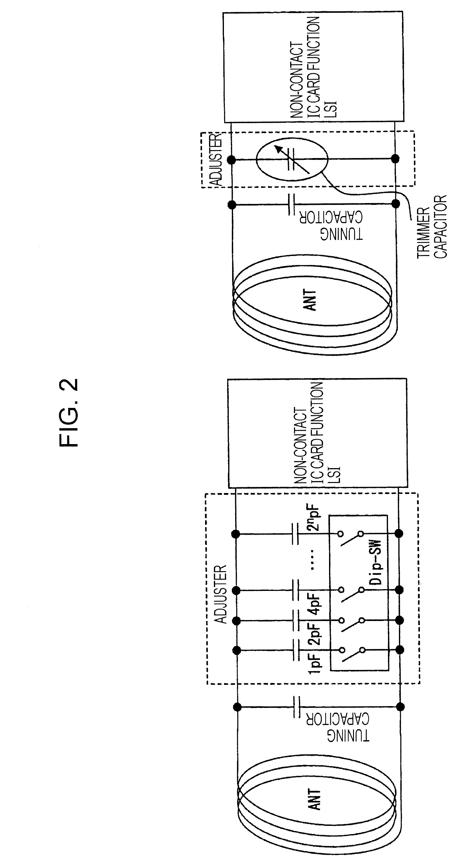
The present invention provides a mobile communication terminal apparatus with a non-contact IC card function that can easily adjust the resonance frequency and reduce the cost of facilities necessary for making adjustments. The apparatus includes a main unit and a sub-unit with a smaller coil, and an adjuster that can adjust the resonance frequency by using at least one adjustment capacitor and a switching element connected in series to each adjustment capacitor. The method of adjusting the resonance frequency includes measuring the resonance frequency, computing the deviation between the measured resonance frequency and a target resonance frequency, and adjusting the resonance frequency based on the deviation. The apparatus and method can reduce power loss and improve carrier wave transmission.

Problems solved by technology

However, even this method does not provide a complete solution to the above problems.
That is, in general, a high voltage (several tens of V) may be applied to a loop antenna for a non-contact IC card, and elements that can be used are limited.
When such a high voltage is applied, a switching element, such as an FET, may be damaged, and the resonance frequency that has been adjusted with effort is varied again.
Furthermore, since the parasitic capacitance of the switching element is a new variation factor, adjustment accuracy becomes poor.
However, in general, in an element having a low on-resistance, since a large number of switches are connected in parallel to each other on the inside, parasitic capacitance is large.
Furthermore, if the non-contact IC card function LSI is used with the balance being broken, it becomes open to influence by extraneous noise.
If a balance method is not used, the problems are solved, but the types of LSI that can be selected are limited.
Furthermore, since it is difficult to perform control unless the electrical potential difference between a control terminal (e.g., the gate of an FET) of a switching element and a GND (e.g., the source of the FET) of the switching element is stabilized, a resonance loop is inevitably formed via the GND, as shown in FIG. 3 (when a mechanical relay is used, this does not apply, however, this is not practical in terms of power consumption and the size of parts).
Since capacitors are provided between at least one of the terminals of the antenna and the GND thereof, when the non-contact IC card function LSI has an R / W function (carrier wave sending function), there is a problem in that power loss occurs when a carrier wave is transmitted.

Method used


Image

  • Wireless communication terminal apparatus and method of controlling same
  • Wireless communication terminal apparatus and method of controlling same
  • Wireless communication terminal apparatus and method of controlling same

Examples


Embodiment Construction

[0034]Embodiments of the present invention will be described below with reference to the attached drawings.

[0035]

[0036]FIG. 4 shows the block configuration of a mobile communication terminal 100 in which a non-contact IC card function is implemented according to an embodiment of the present invention. In FIG. 4, the mobile communication terminal is configured in such a manner that a controller (control means) 5 serves as a central unit, and a digital signal processor 3, a display section 6, an operation section 7, an external I / F section 8, a power-supply unit 9, an RTC (Real Time Clock) 16, and a non-contact IC card section 20 are connected to the controller 5. The controller 5 is a main unit for implementing the functions of the mobile communication terminal, and includes a CPU, an EEPROM, a flash ROM, a RAM, and the like although these are not shown. In this embodiment, the controller 5 further includes a card interface module 51 for transmitting and receiving commands and data t...


PUM


Abstract

A mobile communication terminal apparatus includes a non-contact communication section configured to perform non-contact communication with an external terminal apparatus. The non-contact communication section includes a main unit having a controller configured to control communication with the external terminal apparatus and a main antenna, and a sub-unit having a sub-antenna having a coil whose number of windings is smaller than the number of windings of a coil of the main antenna and an adjuster configured to adjust a resonance frequency.

Description

CROSS REFERENCES TO RELATED APPLICATIONS[0001]The present invention contains subject matter related to Japanese Patent Application JP 2006-160165 filed in the Japanese Patent Office on Jun. 8, 2006, the entire contents of which are incorporated herein by reference.BACKGROUND OF THE INVENTION[0002]1. Field of the Invention[0003]The present invention relates to a wireless communication terminal apparatus having a non-contact IC card function (RFID (Radio Frequency IDentification) function of an electromagnetic induction method) and to a method of adjusting the resonance frequency of an antenna for a non-contact IC card installed in the wireless communication terminal apparatus.[0004]2. Description of the Related Art[0005]In recent years, non-contact IC cards that can be used for various kinds of applications, such as for transportation commuter passes, logging of employees arriving / leaving the office, electronic money, and credit cards, have become popular. Furthermore, functions of s...

Claims


Application Information

Patent Timeline
Patent Type & Authority Applications(United States)
IPC IPC(8): G08B13/14H04B5/48
CPCG06K7/0008G06K19/07767G06K19/0726G06K19/0723
Inventor TSUSHIMA, TAKAAKIHATAKEYAMA, HIDEAKI
Owner SONY CORP
Learn More