
Outboard engine system

a technology of engine system and outboard engine, which is applied in the direction of gearing, motor-driven power plants, vessel construction, etc., can solve the problems of difficulty in reducing costs, and achieve the effect of reducing costs

Inactive Publication Date: 2007-12-13
YUTAKA GIKEN CO LTD
View PDF8 Cites 6 Cited by
  • Summary
  • Abstract
  • Description
  • Claims
  • Application Information

AI Technical Summary

Benefits of technology

[0007] The present invention has been achieved in view of the above problem, and has an object to provide an outboard engine system which enables support of a torque converter without using any bearing exclusively for supporting the overall weight of the torque converter, thereby reducing the cost.

Problems solved by technology

Therefore, the outboard engine system requires an expensive bearing having a large load capacity, leading to a difficulty in reducing the cost.

Method used


Image

  • Outboard engine system
  • Outboard engine system
  • Outboard engine system

Examples


Embodiment Construction

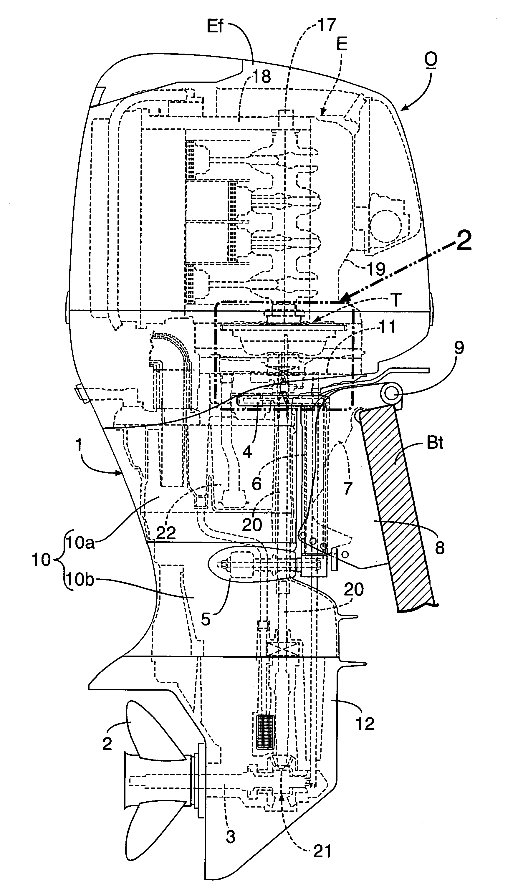
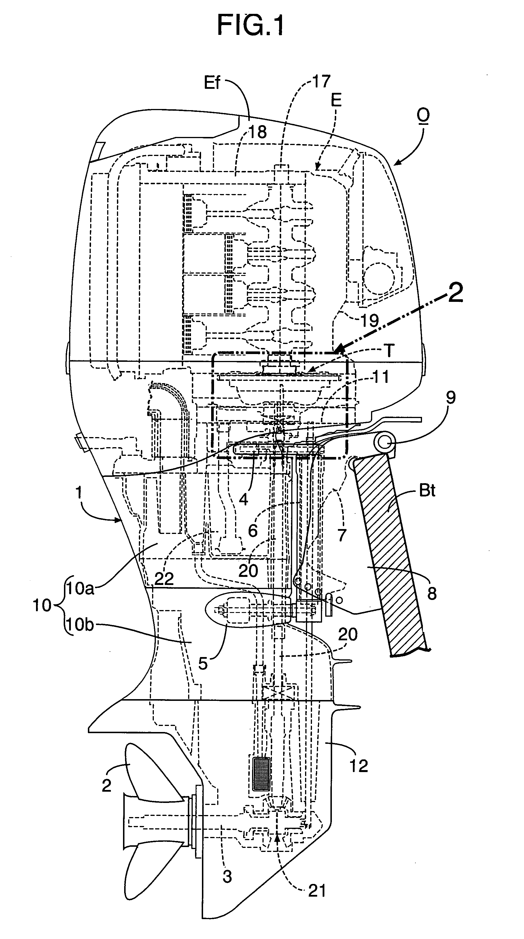
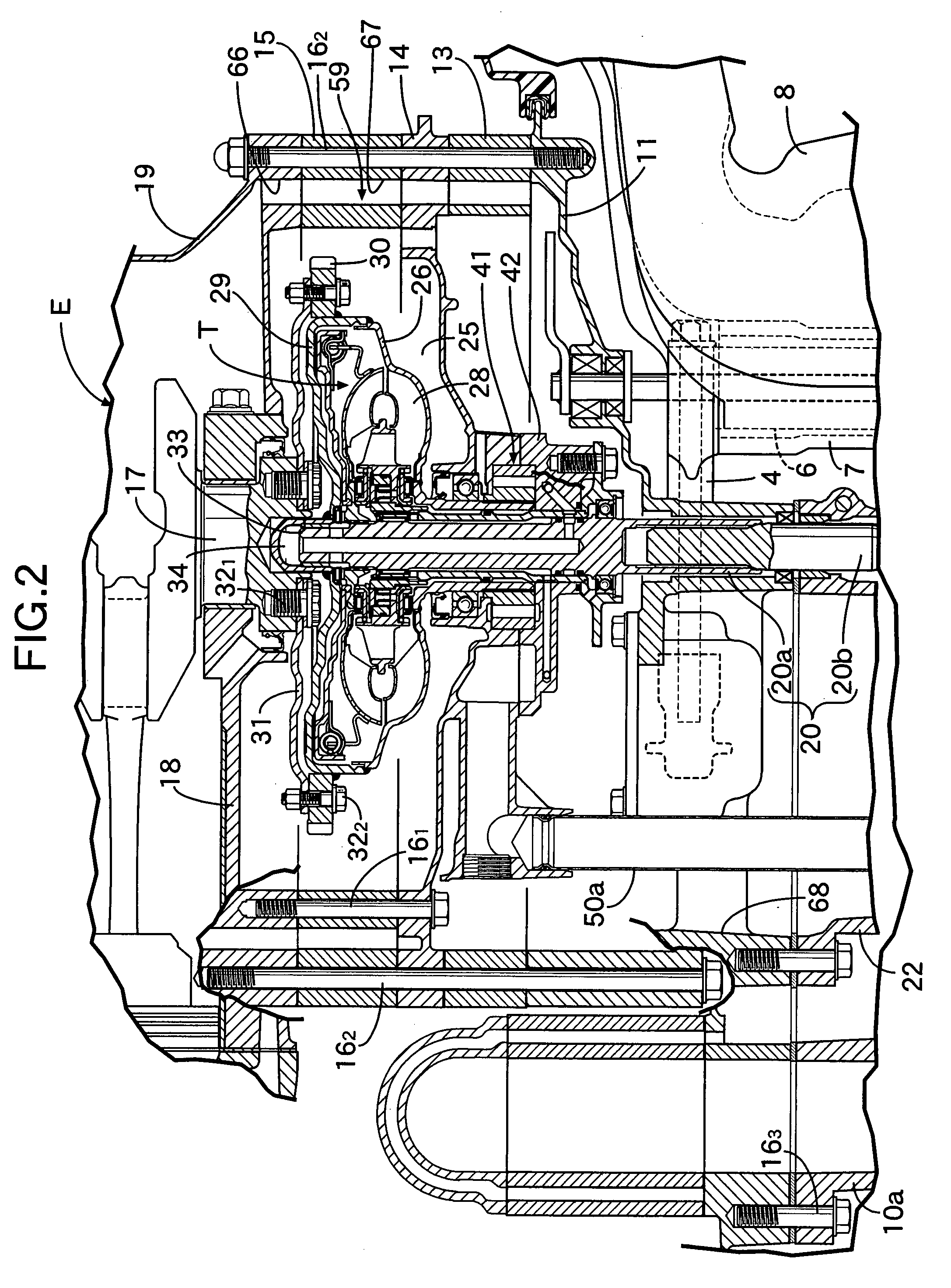
[0038] A first embodiment of the present invention will be described with reference to FIGS. 1 to 6. In FIG. 1, an outboard engine system O includes a casing 1 which has a water-cooled multi-cylinder four-stroke engine E mounted in its upper portion, and supports a propeller shaft 3 at its lower portion. The propeller shaft 3 has a propeller 2 provided at its rear end. A vertically-extending swivel shaft 6 is mounted to the casing 1 via an upper arm 4 and a lower arm 5 so as to situate in front of the casing 1. The swivel shaft 6 is rotatably supported by a swivel case 7 which is coupled to a stern bracket 8 via a horizontally-extending tilt shaft 9. The stern bracket 8 is cramped to a transom Bt of a body of a ship. Therefore, the casing 1 is horizontally rotatable around the swivel shaft 6, and vertically tiltable around the tilt shaft 9. The reference numeral Ef denotes a removable engine hood for covering the engine E.

[0039] In FIG. 1 and FIG. 2, the above casing 1 includes the...


PUM


Abstract

An outboard engine system includes a casing and an engine mounted in an upper part of the casing. The casing also contains a torque converter, and a vertically arranged output shaft connected to a crankshaft through the torque converter. In the torque converter, a turbine runner is arranged above a pump impeller and connected to the output shaft, and a transmission cover is connected to an outer periphery of the pump impeller so as to cover an upper surface of the turbine runner. A drive plate is secured at its central portion to a lower end of the crankshaft by a first bolt, and an outer peripheral portion of the drive plate is secured to the transmission cover by a second bolt. The torque converter is suspended from the crankshaft via the drive plate. Thus, it is possible to provide an outboard engine system which enables support of a torque converter without using any bearing exclusively for supporting the overall weight of the torque converter, thereby reducing the cost.

Description

RELATED APPLICATION DATA [0001] The present invention is based upon Japanese priority application Nos. 2006-145972, 2006-145973 and 2006-145974 which are hereby incorporated in their entirety herein by reference. BACKGROUND OF THE INVENTION [0002] 1. Field of the Invention [0003] The present invention relates to an outboard engine system comprising: a casing coupled to a swivel case via a swivel shaft; an engine mounted in an upper part of the casing such that a crankshaft of the engine is vertically arranged and a cylinder block of the engine faces in a direction opposite to the swivel shaft; a torque converter; a vertically arranged output shaft connected to the crankshaft through the torque converter; a horizontally arranged propeller shaft provided below the output shaft; and a forward-reverse shifting gear mechanism for providing a connection between the output shaft and the propeller shaft; the torque converter, the output shaft, the propeller shaft and the forward-reverse shi...

Claims


Application Information

Patent Timeline
Patent Type & Authority Applications(United States)
IPC IPC(8): B63H21/12
CPCB63H20/14B63H20/20B63H23/26B63H23/30F16H2041/243F16H41/24F16H41/28F16H45/02B63H2023/305
Inventor MIYATA, TAKAHIROYOSHIMOTO, TOKUJI
Owner YUTAKA GIKEN CO LTD
Learn More