Dust collecting apparatus for vacuum cleaner
a technology for collecting apparatus and vacuum cleaner, which is applied in the direction of auxillary pretreatment, cleaning filter means, separation processes, etc., can solve the problems of increasing the size of the dust collecting apparatus and the suction force of the cleaner, and achieves the effect of improving visibility
- Summary
- Abstract
- Description
- Claims
- Application Information
AI Technical Summary
Benefits of technology
Problems solved by technology
Method used
Image

Examples
first embodiment
[0027]A dust collecting apparatus for a vacuum cleaner of the present disclosure will be described in greater detail with reference to the accompanying drawings. The dust collecting apparatus is generally referred to by reference numeral 1.
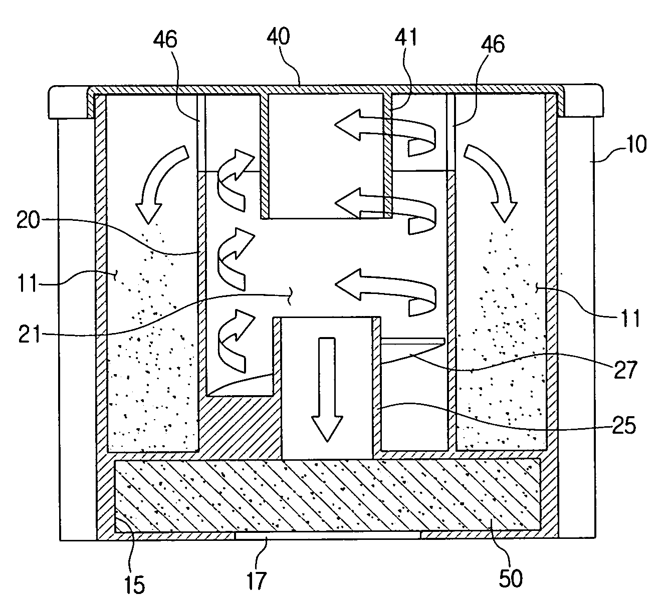
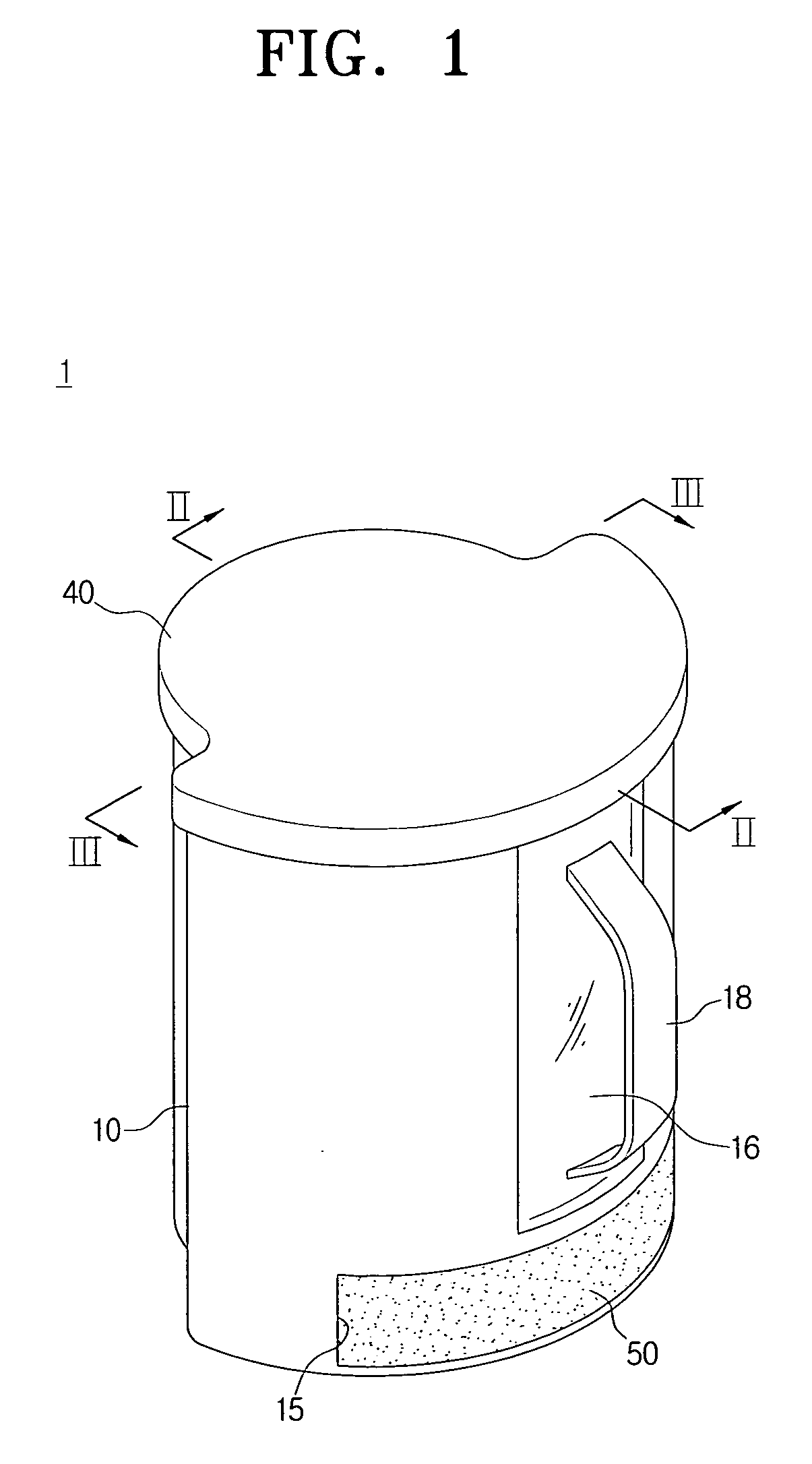
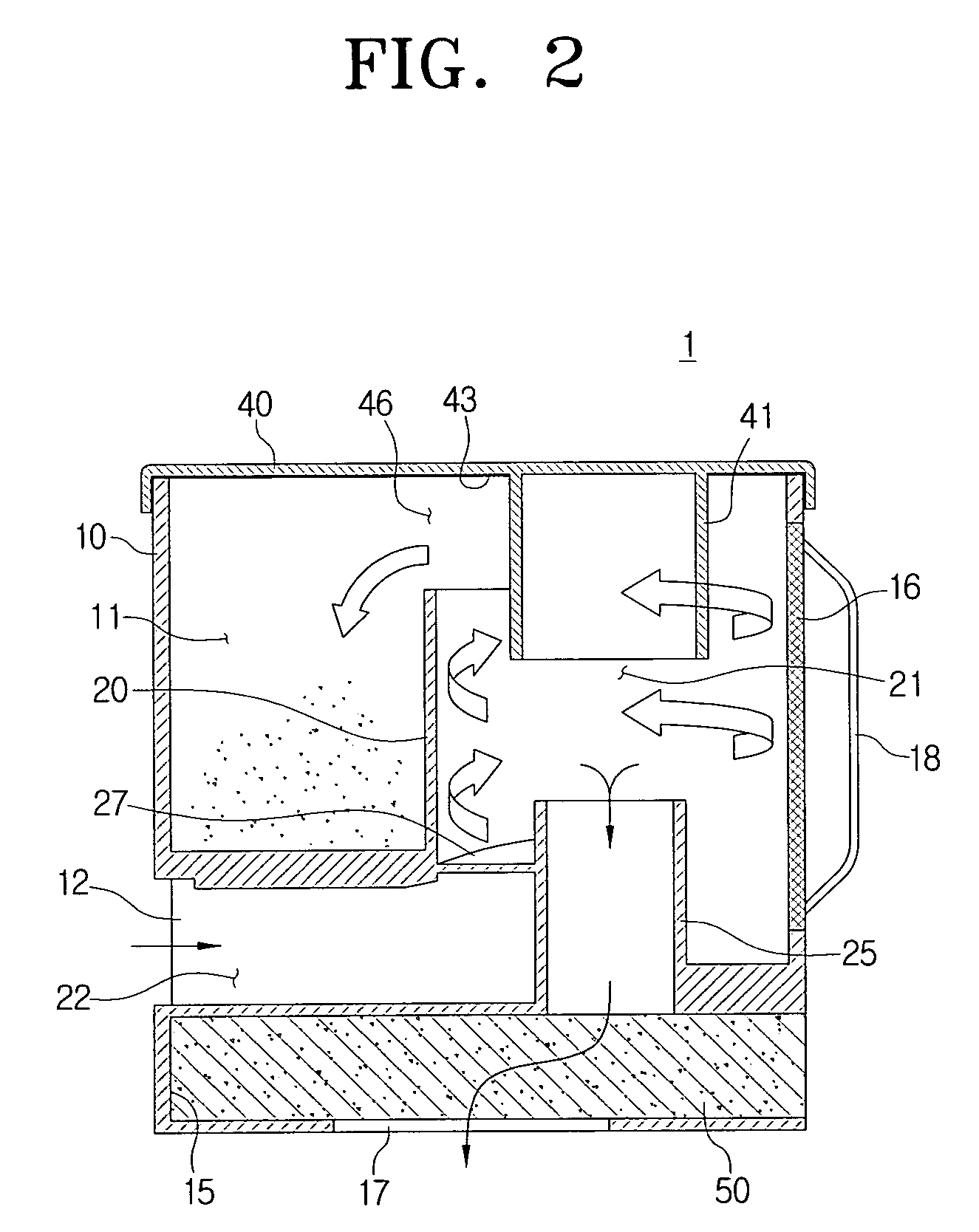
[0028]FIGS. 1 to 4 illustrate first embodiment of a dust collecting apparatus 1 of the present disclosure. FIG. 1 is a perspective-view illustrating a state that a cover 40 is coupled with a dust canister body 10, FIG. 2 is a cross-sectional view taken along a line II-II shown in FIG. 1, FIG. 3 is a cross-sectional view taken along a line III-III shown in FIG. 1, and FIG. 4 is a plan view illustrating a state that the dust collecting apparatus shown in FIG. 2 is uncovered.
[0029]Firstly, the dust collecting apparatus 1 according to the first embodiment of the present disclosure includes a dust canister body 10, a cyclone body 20 and a cover 40, as shown in FIGS. 1 to 4.
[0030]The dust canister body 10 is configured of a generally step-like cylindri...
third embodiment
[0039]Furthermore, FIG. 7 illustrates the present disclosure wherein the cyclone body 220 can be arranged eccentrically to an opposite side of the exposure surface E, where the exposure surface E and the cyclone body 220 are preferably made of transparent materials in order to enhance visibility of the cyclone body 220. In addition, the helical guide 227 is preferably colored lighter than the cyclone body 220 in order to apparently observe the process of the dust flowing into the cyclone chamber 221, which results in maximizing visibility. Reference numeral 225 of FIG. 7 refers to the outlet pipe.
fourth embodiment
[0040]Furthermore, as shown in FIGS. 1 to 7, the above embodiments were described as examples in which the cyclone body 20, 120, 220 is arranged as single body within the dust collection chamber 11, while the present disclosure, shown in FIG. 8, is configured such that the cyclone body includes of a pair of bodies 320a, 320b. Herein, a portion of each of the pair of cyclone body 320a, 320b may be arranged to be protruded from the dust canister body 310 within the dust collection chamber 311a, 311b. In this case, the pair of cyclone bodies 320a, 320b cause the air to flow via a pair of air inlet passages 312a, 312b that run through one side of the dust canister body 310, respectively. Furthermore, the dust collection chambers 311a, 311b are divided by a partition 330 so that the dust discharged from the pair of cyclone bodies 320a, 320b is collected into the dust collection chambers 311a, 311b respectively. Reference numeral 321a and 321b refer to the cyclone chamber, and 327a and 32...
PUM
| Property | Measurement | Unit |
|---|---|---|
| Force | aaaaa | aaaaa |
| Transparency | aaaaa | aaaaa |
| Exposure limit | aaaaa | aaaaa |
Abstract
Description
Claims
Application Information
 - R&D
- Intellectual Property
- Life Sciences
- Materials
- Tech Scout
- Unparalleled Data Quality
- Higher Quality Content
- 60% Fewer Hallucinations
Browse by: Latest US Patents, China's latest patents, Technical Efficacy Thesaurus, Application Domain, Technology Topic, Popular Technical Reports.
© 2025 PatSnap. All rights reserved.Legal|Privacy policy|Modern Slavery Act Transparency Statement|Sitemap|About US| Contact US: help@patsnap.com