Dispensing valve

a valve and dispensing technology, applied in the field of self-sealing valves, can solve the problems of inconsistent dispensing characteristics, valves constructed from most conventional plastic materials, and valves that cannot be used in at least certain types of packages

Inactive Publication Date: 2007-12-20
APTARGROUP INC
View PDF21 Cites 13 Cited by
  • Summary
  • Abstract
  • Description
  • Claims
  • Application Information

AI Technical Summary

Benefits of technology

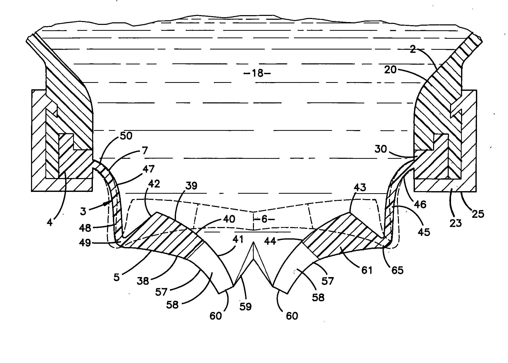
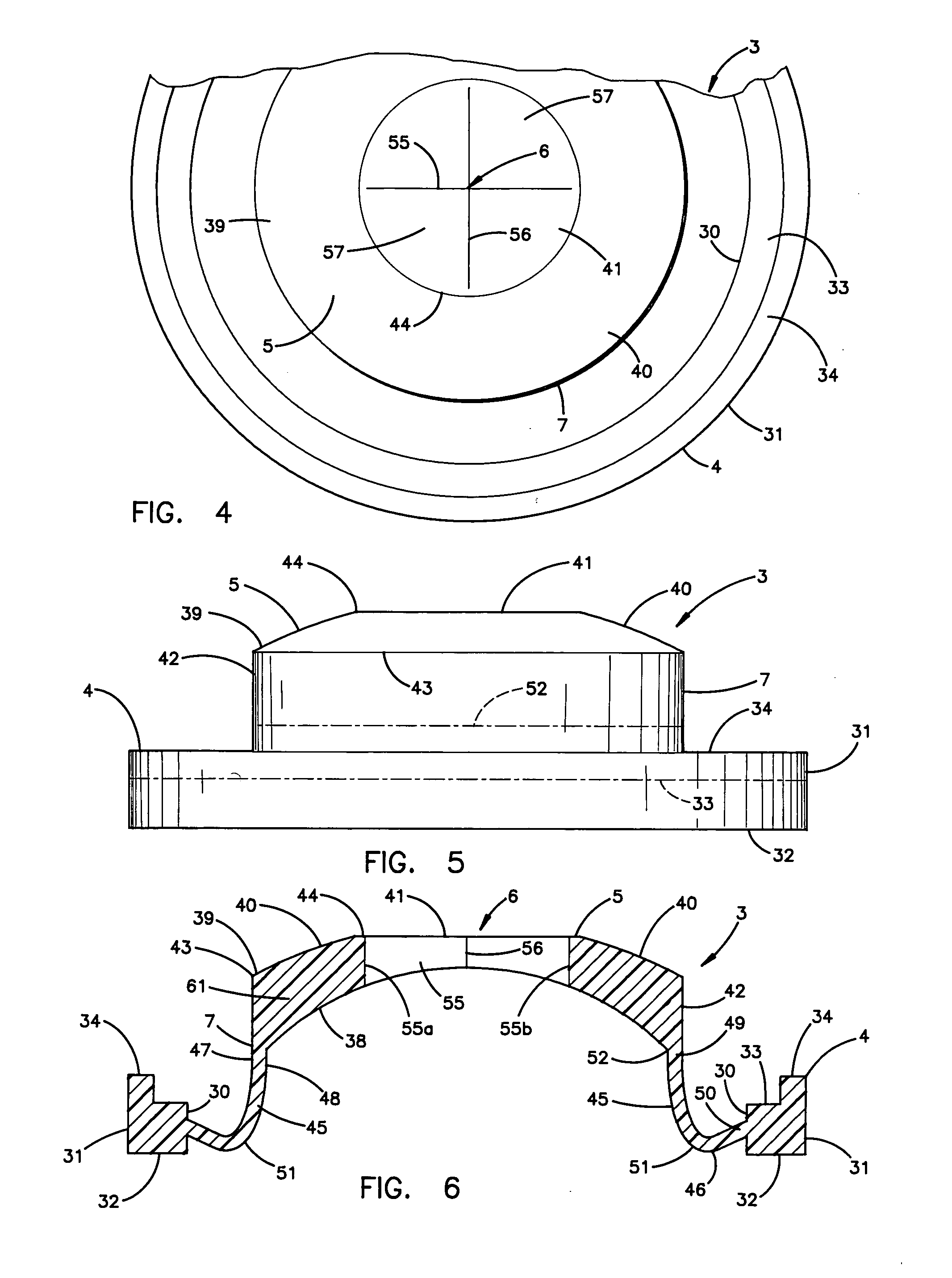
[0010] Another aspect of the present invention is a dispensing valve for fluid product packaging and the like, having a marginal valve flange shaped to seal about a discharge opening of the container. The valve includes a valve head having a marginal edge, interior and exterior sides, and an orifice extending therebetween which opens to permit fluid flow therethrough in response to communication with a predetermined discharge pressure, and closes to shut off fluid flow therethrough upon removal of the predetermined discharge pressure. A connector sleeve with a resiliently flexible construction, has one end connected with the valve flange, and the opposite end connected with the valve head adjacent to the marginal edge thereof, whereby when pressure in excess of the predetermined discharged pressure is applied to the interior side of the valve head, the valve head shifts outwardly in a manner which causes the connector sleeve to double over and then extend rollingly, and thereby apply a torque to the valve head which assists in opening the orifice.
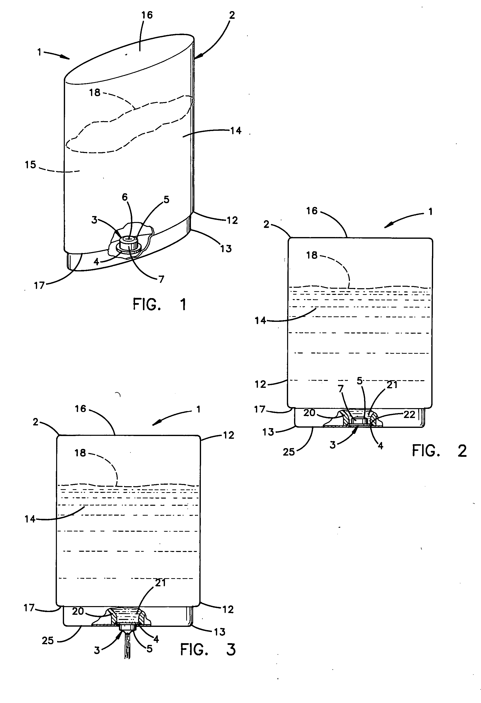
[0021] The principal objects of the present invention are to provide a dispensing package and an associated self-sealing valve which are capable of easily and neatly dispensing a wide variety of different types of fluid products. The self-sealing valve is matched with both the container and the type of fluid product to be dispensed, so as to quickly and securely seal, yet readily and fully open when the user applies modest pressure to the container. In preferred embodiments, the valve includes a resiliently flexible connector sleeve which is configured to apply a torque to the valve head which assists in opening the orifice. The connector sleeve has sufficient flexibility that pressure increases in the interior of the container, such as those caused by thermal expansion, are offset by shifting the valve head on the connector sleeve, so as to alleviate excess pressure on the orifice. The connector sleeve is also configured to provide sufficient flexibility that any misalignment and / or distortion of the valve flange when attached to the associated container are not transmitted to the valve head, thereby permitting unhindered opening and closing of the orifice. The connector sleeve is also configured to provide sufficient flexibility that shock impact forces, and the like applied to the container are absorbed by shifting the valve head on the connector sleeve, so as to avoid inadvertent opening of the valve orifice. The valve is configured to provide a generally constant flow rate therethrough, even when exposed to a relatively wide range of container pressures. For those products wherein a substantial amount of material is typically dispensed per application, the valve is configured such that once the orifice is shifted open, the amount of pressure required to maintain fluid flow through the orifice is reduced, so as to provide greater ease of operation, without sacrificing secure sealing of the valve. The valve is extremely versatile, and may be used in either top, bottom or side dispensing packages to accommodate a wide variety of different applications. The valve is very durable, while having reduced manufacturing costs, and an uncomplicated design. design. The overall package is efficient in use, economical to manufacture, capable of a long operating life, and particularly well adapted for many different proposed uses.

Problems solved by technology

However, such valves have been known to experience some types of sealing problems, and inconsistent dispensing characteristics, particularly when the packages are exposed to significant temperature variations.
Valves constructed from most conventional plastic materials cannot be used in at least certain types of packages, since they either react with or adulterate the product.
Furthermore, active ingredients in products can cause the valve to either embrittle or soften, thereby ruining the designed flow rate and / or self-sealing characteristics of the valve.
Although liquid silicone rubber possesses many attributes for use in packaging, it also has other characteristics which render such applications problematic.
For example, the surfaces of liquid silicone rubber parts are extremely tacky or sticky, having a very high coefficient of friction.
Tightening of the collar often causes the valve flange, as well as the entire valve to distort from its designed shape, thereby preventing the formation of a secure seal, and / or changing the intended dispensing and sealing characteristics of the valve.
Another drawback associated with the use of liquid silicone rubber in dispensing valves for product packaging is that there is presently no available adhesive capable of connecting the valve to a container in a manner that will withstand the operating pressures to which the valve and container are repeatedly subjected.
Another problem experienced with prior dispensing packages relates to achieving a proper design balance between the package container, valve, and fluid product, so that the product can be repeatedly dispensed without requiring excess force, and will neatly discharge only that amount of product which is desired by the user, particularly in keeping with the type of product involved.
For instance, when dispensing highly concentrated fluid products, such as hand soaps, and the like, the user will typically require only a small amount or dollop of soap per application to achieve satisfactory results.

Method used


Image

  • Dispensing valve
  • Dispensing valve
  • Dispensing valve

Examples


Embodiment Construction

[0055] For purposes of description herein, the terms “upper”, “lower”, “right”, “left”, “rear”, “front”, “vertical”, “horizontal”, and derivatives thereof shall relate to the invention as oriented in FIGS. 1-3. However, it is to be understood that the invention may assume various alternative orientations and step sequences, except where expressly specified to the contrary. It is also to be understood that the specific devices and processes illustrated in the attached drawings, and described in the following specification are simply exemplary embodiments of the inventive concepts defined in the appended claims. Hence, specific dimensions and other physical characteristics relating to the embodiments disclosed herein are not to be considered as limiting, unless the claims expressly state otherwise. considered as limiting, unless the claims expressly state otherwise.

[0056] The reference numeral 1 (FIG. 1) generally designates a dispensing package embodying the present invention. Dispe...


PUM


Abstract

A dispensing valve is provided for dispensing fluid products. The valve includes a marginal portion, a flexible valve head portion with a discharge orifice therein, and a flexible connector sleeve having one end connected with the valve marginal portion and the opposite end connected with the valve head portion adjacent a marginal edge thereof.

Description

CROSS-REFERENCES TO RELATED APPLICATIONS [0001] The present application is a continuation of commonly assigned, co-pending U.S. patent application Ser. No. 10 / 180,746, filed Jun. 26, 2002, entitled “DISPENSING VALVE,” (Parent Application), which is a continuation of Ser. No. 09 / 812,129, filed Mar. 19, 2001, entitled “DISPENSING VALVE,” now U.S. Pat. No. 6,427,874 (Grandparent Application), which is a continuation of Ser. No. 08 / 886,567, filed Jul. 1, 1997, entitled “DISPENSING PACKAGE,” now U.S. Pat. No. 6,279,783 (Great Grandparent Application), which is a continuation of Ser. No. 08 / 508,472, entitled “DISPENSING PACKAGE,” filed Jul. 28, 1995, now U.S. Pat. No. 5,839,614, (Great Great Grandparent Application), which is a continuation-in-part of Ser. No. 08 / 240,264, filed May 10, 1994, entitled “DISPENSING PACKAGE,” now U.S. Pat. No. 5,439,143 (Great Great Great Grandparent Application), which is a continuation of Ser. No. 08 / 39,896, filed Mar. 30, 1993, now U.S. Pat. No. 5,339,995 ...

Claims


Application Information

Patent Timeline
Patent Type & Authority Applications(United States)
IPC IPC(8): F16K15/14B67D7/06B65D35/52B65D47/20B65D83/00
CPCF16K15/147B65D47/2031Y10T137/788B67D7/06F16K15/1471F16K15/1472
Inventor BROWN, PAUL E.SOCIER, TIMOTHY R.
Owner APTARGROUP INC
Why Eureka
Try Eureka