Adjustable smooth bore nozzle

a smooth bore, adjustable technology, applied in the direction of diaphragm valves, engine diaphragms, mechanical equipment, etc., can solve the problems of bore nozzles, fixed diameter, limited flow rate range,

Inactive Publication Date: 2007-12-20
ELKHART BRASS MFG
View PDF27 Cites 14 Cited by
  • Summary
  • Abstract
  • Description
  • Claims
  • Application Information

AI Technical Summary

Benefits of technology

[0006] Accordingly, the present invention provides a nozzle that has an adjustable bore and, therefore, can vary the flow rate through the nozzle without requiring the flow to be shut off. In other words, the present invention provides a nozzle that is adapted to have its bore diameter adjusted while still in a flow condition.
[0015] In another aspect, the tip includes an inner surface, with the flexible bladder expandable up to the inner surface of the tip in response to increased pressure in the passageway wherein the inner dimension of the flexible membrane increases to thereby increase the flow rate through the nozzle.
[0019] Accordingly, the present invention provides a smooth bore nozzle with an adjustable diameter so that the flow rate through the nozzle can be achieved during a flow condition.

Problems solved by technology

One disadvantage to smooth bore nozzles is that they have a fixed diameter.
As a result, they provide a limited flow rate range, with the fluid pressure driving the flow rate change.
However, in either case this requires the user to shut off the water supply when changing the nozzle or adding or removing a fitting to change the nozzle diameter.
As a result, this can create downtime for the firefighter.

Method used


Image

  • Adjustable smooth bore nozzle
  • Adjustable smooth bore nozzle
  • Adjustable smooth bore nozzle

Examples


first embodiment

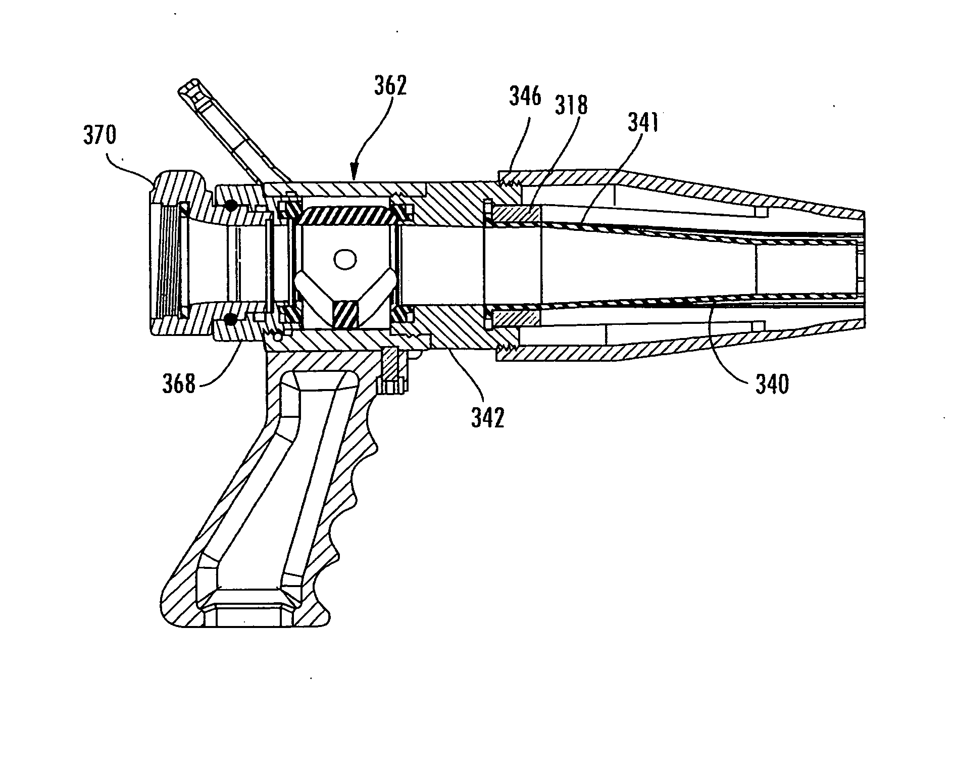
[0059] To adjust the inner diameter of tapered body portion 224 of nozzle body 218, nozzle 210 similarly includes an adjustment tip 246. Adjustment tip 246 comprises a conical-shaped body that is threaded onto adapter 242 and includes a tapered wall 248 spaced from tapered wall 234 with a recessed portion 249 that forms a shoulder 250 adjacent and spaced inwardly from its outer end. Recessed portion 249 contacts the outer ends of the tapered wall's fingers or beams 239 and forms a ramped or cam interface with beams 239. In the illustrated embodiment, each of the beams includes a ramped surface 252, such as a wedge-shaped end, that provides a contact surface for recessed portion 249 of adjustment tip 246. In this manner, when adjustment tip 246 is rotated about coupler 242, recessed portion 249 will translate along ramped surfaces 252, which will cause fingers or beams 239 to compress inwardly when adjustment tip 246 is retracted onto coupler 242 but will allow fingers or beams 239 t...

fifth embodiment

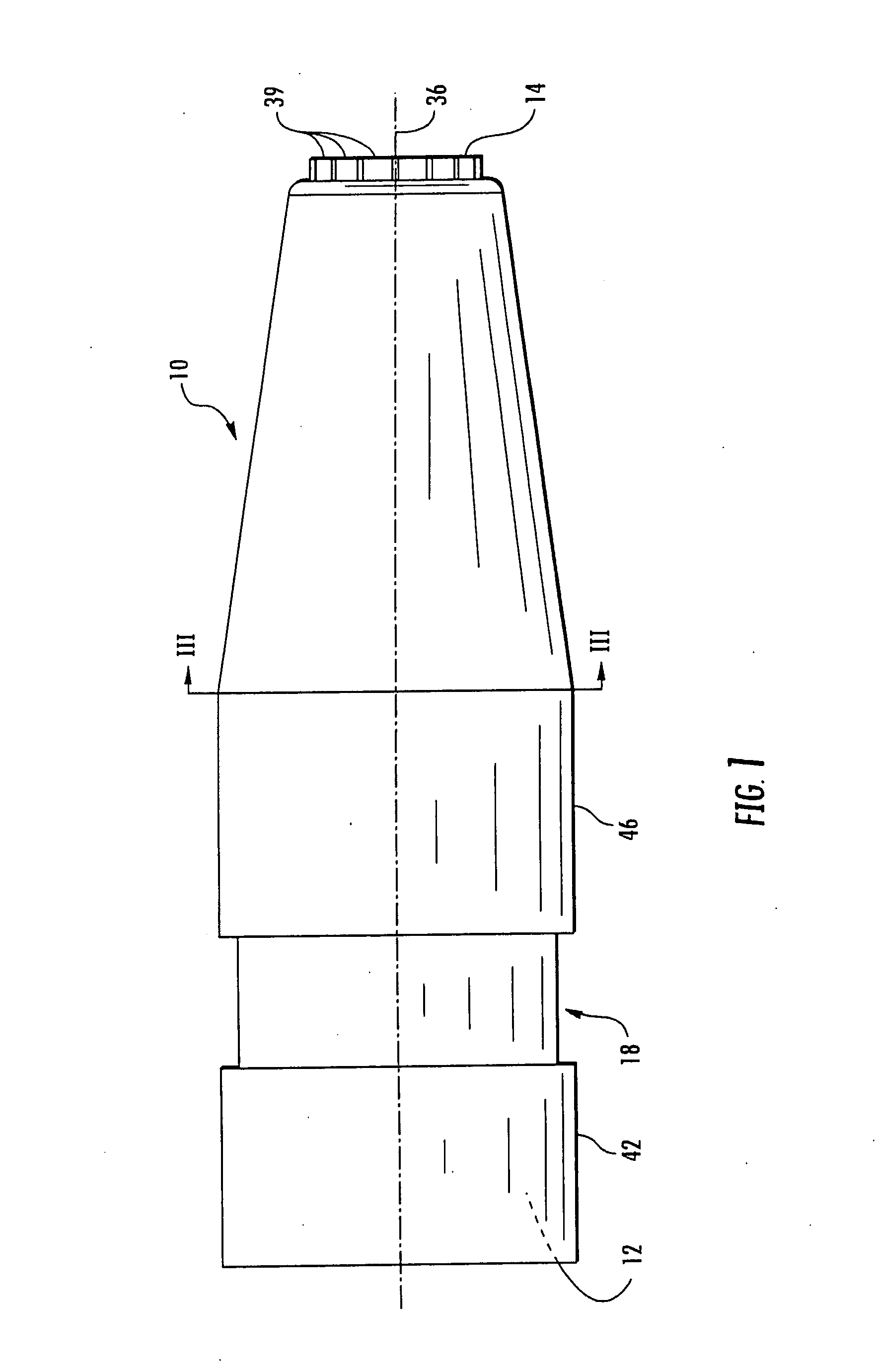
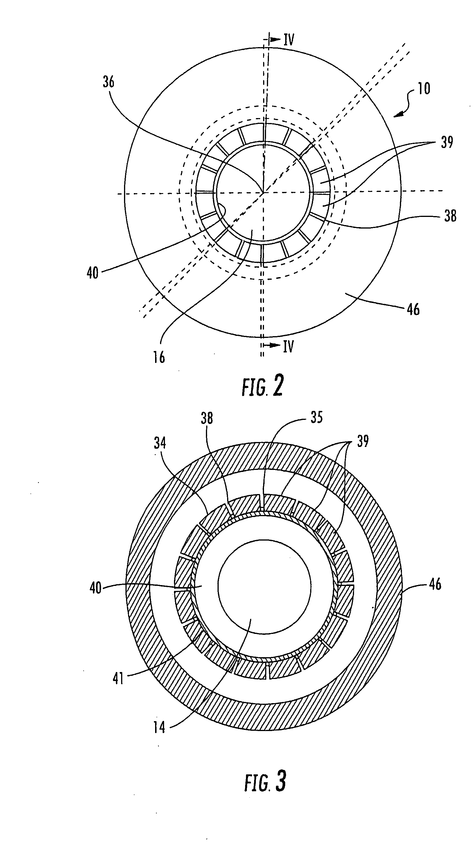
[0066] Referring to FIGS. 15 and 16, the numeral 410 generally designates the nozzle of the present invention. Nozzle 410 is similar to nozzles 210 and 310 and include a nozzle body 418, an adapter 442 for mounting a valve 462 to nozzle body 418, and a second adapter 468 for receiving a hose coupler for mounting nozzle 410 to a hose.

[0067] In the illustrated embodiment, nozzle body 418 includes a cylindrical body portion 422 and a tapered body portion 424, both with fixed diameters. The flexible wall in nozzle 410 is provided by membrane 440. Membrane 440 is mounted to the inlet end of cylindrical body portion 422, for example, by molding, and extends through the passage 430 of tapered body portion 424 to form flow passage 416. In this application, similar to nozzle 110, when membrane 440 is pressurized, membrane 440 will expand radially outward until it reaches the inner surface 424a of tapered body portion 424. For further details of nozzle 410, reference is made to the previous e...


PUM


Abstract

An adjustable nozzle comprising a nozzle body with an inlet, an outlet, and a passageway having a smooth bore extending between the inlet and the outlet. The passageway has an inner dimension transverse to the central axis of the nozzle and a compressible wall wherein the inner dimension is adjustable to adjust the flow rate through the nozzle.

Description

CROSS-REFERENCE TO RELATED APPLICATIONS [0001] This application is a continuation application of pending U.S. patent Ser. No. 11 / 036,621, filed Jan. 14, 2005, entitled ADJUSTABLE SMOOTH BORE NOZZLE, by Applicants Eric Combs and Todd Lozier, which is incorporated by reference herein in its entirety.TECHNICAL FIELD AND BACKGROUND OF THE INVENTION [0002] The present invention generally relates to a nozzle and, more particularly, to a nozzle that has an adjustable smooth bore. [0003] Smooth bore nozzles are well known in the art and are configured with a gradually diminishing inner diameter from their input end to their discharge or output end to increase fluid flow from a fire hose on which the nozzle is mounted. One disadvantage to smooth bore nozzles is that they have a fixed diameter. As a result, they provide a limited flow rate range, with the fluid pressure driving the flow rate change. For example, a one inch diameter smooth bore nozzle will flow approximately 184 gallons per mi...

Claims


Application Information

Patent Timeline
Patent Type & Authority Applications(United States)
IPC IPC(8): B05B1/32
CPCA62C31/03B05B1/32B05B1/30Y10S239/12A62C31/02B05B1/323
Inventor COMBS, ERICLOZIER, TODD
Owner ELKHART BRASS MFG
Why Eureka
Try Eureka