
Spine tensioning support chair

a support chair and spine technology, applied in the field of physical therapy devices, can solve the problems of inability to provide spine tensioning, difficult for some users, and pain in the back, and achieve the effect of simplifying access

Inactive Publication Date: 2007-12-20
WALTER BRIAN ANTHONY
View PDF5 Cites 9 Cited by
  • Summary
  • Abstract
  • Description
  • Claims
  • Application Information

AI Technical Summary

Benefits of technology

"The invention is a spine tensioning chair that allows users to practice spine tensioning, traction, and development in a simplified and cost-effective way. The chair has two rotating body supports that can be adjusted to different elevations and rotational positions to provide different levels of support for the spine. This allows users to perform various spine tensioning, traction, and developing exercises while sitting in the chair. The chair also has a reclined position that decompresses the low back and a computer input function that allows users to perform computer-related tasks while in the chair. Overall, the invention provides a convenient and effective tool for spine healthcare and wellness."

Problems solved by technology

However, it cannot provide spine tensioning because it supports the user's posterior.
This feat is difficult for some users and may prohibit older users and those with back pain from obtaining the benefits of the device.

Method used


Image

  • Spine tensioning support chair
  • Spine tensioning support chair
  • Spine tensioning support chair

Examples


Embodiment Construction

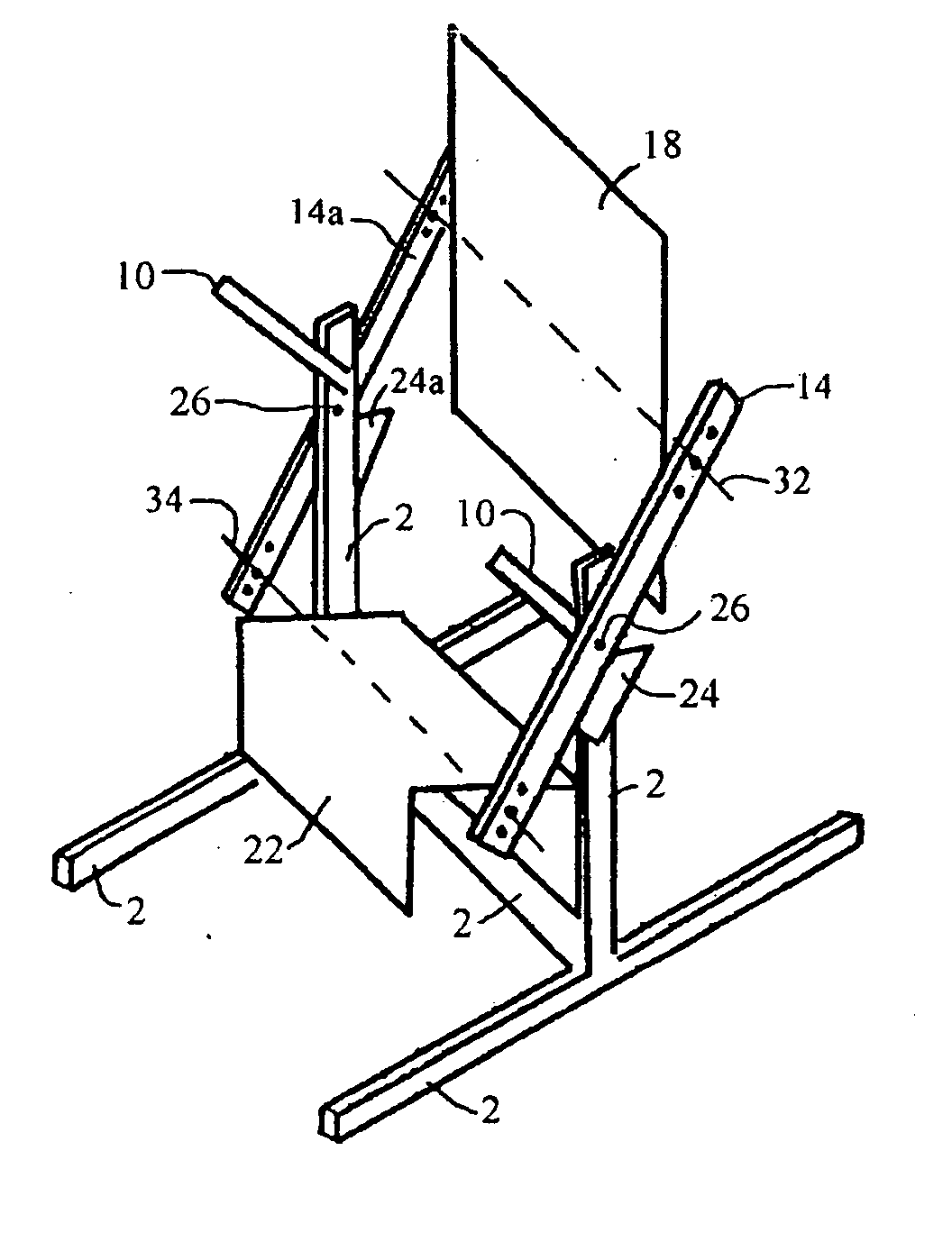
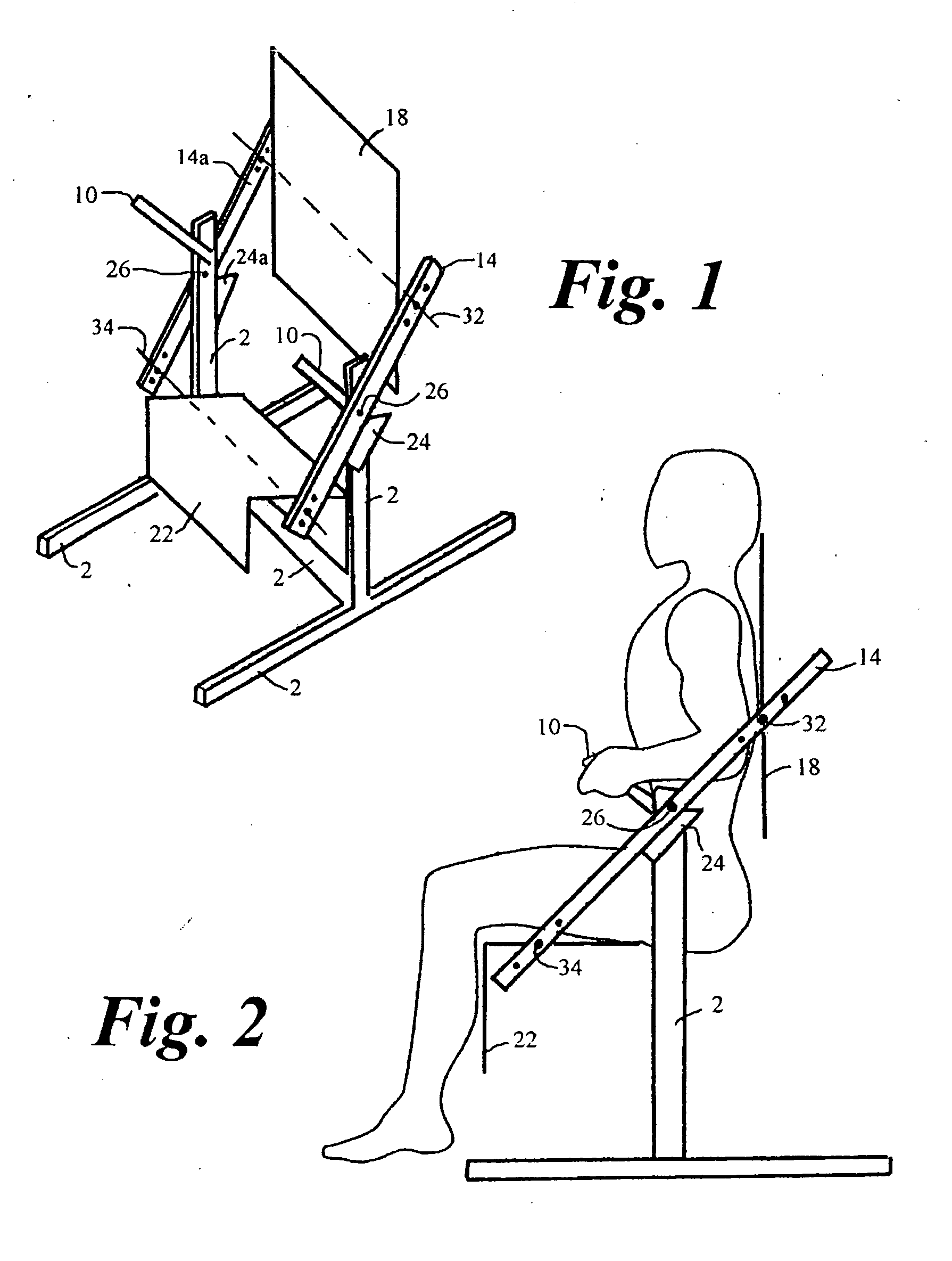
[0136] Referring to FIG. 1, the apparatus comprises a base member 2, consisting of two parallel elongated horizontal base members, two vertical risers, and a horizontal base member perpendicular to and connecting the two elongated horizontal base members. Body support elevation arms 14, 14a are elongated members pivotally mounted to base member 2 via pivot connection 26. Dual body supports, 18 and 22, are pivotally mounted to body support elevation arms 14 and 14a via support rods 32 and 34. Hand grips 10 and body support elevation limit blocks 24 and 24a are attached to base member 2.

[0137]FIG. 2 shows a user in the sitting position. The elevation of body support 18 is higher than body supports 22 creating a chair or seated position. A fixed, stable seat is created when body support elevation arm 14 rests on body support elevation limit block 24.

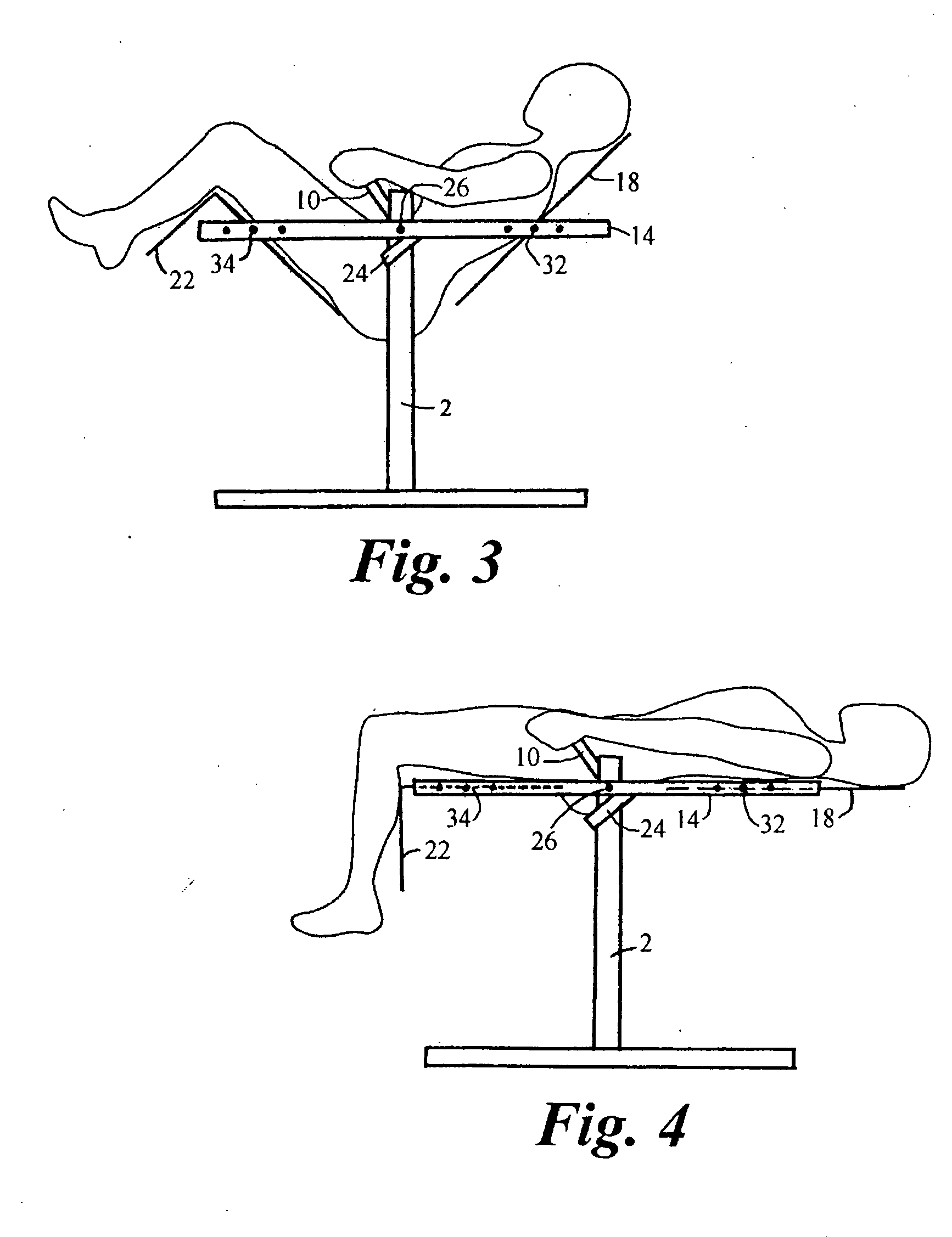
[0138]FIG. 3 shows the user in the reclined seated position dual body supports at near equal elevation. A fixed, stable, reclined positi...


PUM


Abstract

A chair has two independent body supports which move in similar rotation and inverse elevation to one another to change from a chair configuration, one support higher than the other, to a spine tensioning apparatus, supports near equal in elevation. Preferably body supports are spaced apart from one another such that the only interconnecting human link between the two supports, when in a near equal elevation configuration, is the human spine. The spine, in this configuration is then subjected to similar forces as a simple beam supported by two separate forces, tension, compression, shear and moment. The spine is aided by and through tension and compression and increased blood flow and afforded the ability for spinal muscle, nerve and soft tissue development and maintenance. The supports, independent of each other, comprise an upper body support and a lower body support and allow an individual's body to practice spine enhancement, development, & or traction, laying in any combination of, or alternately, face up, face down, or on either left or right side. The apparatus is also applicable to retrofitting existing chairs.

Description

[0001] This is a Division of application Ser. No. 08 / 944,945 wherein applicant elects Species No. 8, Fig. No. 21, of the Parent Issued U.S. Pat. No. 6,435,611, for prosecution. CROSS REFERENCE TO RELATED APPLICATIONS [0002] Provisional application No. 60 / 027,767, filed on Oct. 4, 1996.STATEMENT REGARDING FEDERALLY SUPPORTED RESEARCH OR DEV [0003] Not applicable. REFERENCE TO A SEQUENCE LISTING, A TABLE, ETC [0004] Not applicable. BACKGROUND OF THE INVENTION [0005] This invention relates generally to devices used in physical therapy and, more particularly, to a spine tensioning, traction and muscle exercise apparatus. [0006] Back pain is a national health problem. It is the second most likely reason people go to the doctor. It is estimated Americans spent $20 billion alone in 1990 on back-related medical bills. More and more people sit for hour upon hour and perform computer work. Studies show that sitting creates two times the pressure on the low back as compared to standing. [0007]...

Claims


Application Information

Patent Timeline
Patent Type & Authority Applications(United States)
IPC IPC(8): A47C3/00A47C1/00A47C9/00A61H1/02A61H37/00B60N2/02
CPCA47C9/002A61H1/0222B60N2/0292A61H2203/0431A61H2203/0456A61H37/005
Inventor WALTER, BRIAN ANTHONY
Owner WALTER BRIAN ANTHONY
Learn More