Computer generated hologram display system

a technology of computer generated holograms and display systems, applied in the field of computer generated hologram display systems, can solve problems such as non-uniform density of object points across facet boundaries

Inactive Publication Date: 2007-12-20
MIND FUSION LLC
View PDF52 Cites 0 Cited by
  • Summary
  • Abstract
  • Description
  • Claims
  • Application Information

AI Technical Summary

Benefits of technology

[0013] The current invention discloses an object point arrangement having a grid, wherein the actual object points are not confined to being on the nodes of the grid. It has been found that random perturbations of points from the grid improves the behaviour of points at facet borders. Such a grid arrangement has the characteristic that it can be abutted to other orientations of itself whilst only having a minor effect on the point density in the region of the shared edge. Thus one facet having a particular grid orientation can adjoin another facet having a different orientation with little apparent change in point density.
[0015] The invention therefore provides a way to have the minimal density of points consistent with the resolving abilities of the human eye, yet avoid localised overpopulation or underpopulation of the object surface.

Problems solved by technology

This leads to problems of non uniform density of object points across facet boundaries: too high a density will produce a bright area, whereas too low a density will produce a dark area on the object.

Method used


Image

  • Computer generated hologram display system
  • Computer generated hologram display system
  • Computer generated hologram display system

Examples


Embodiment Construction

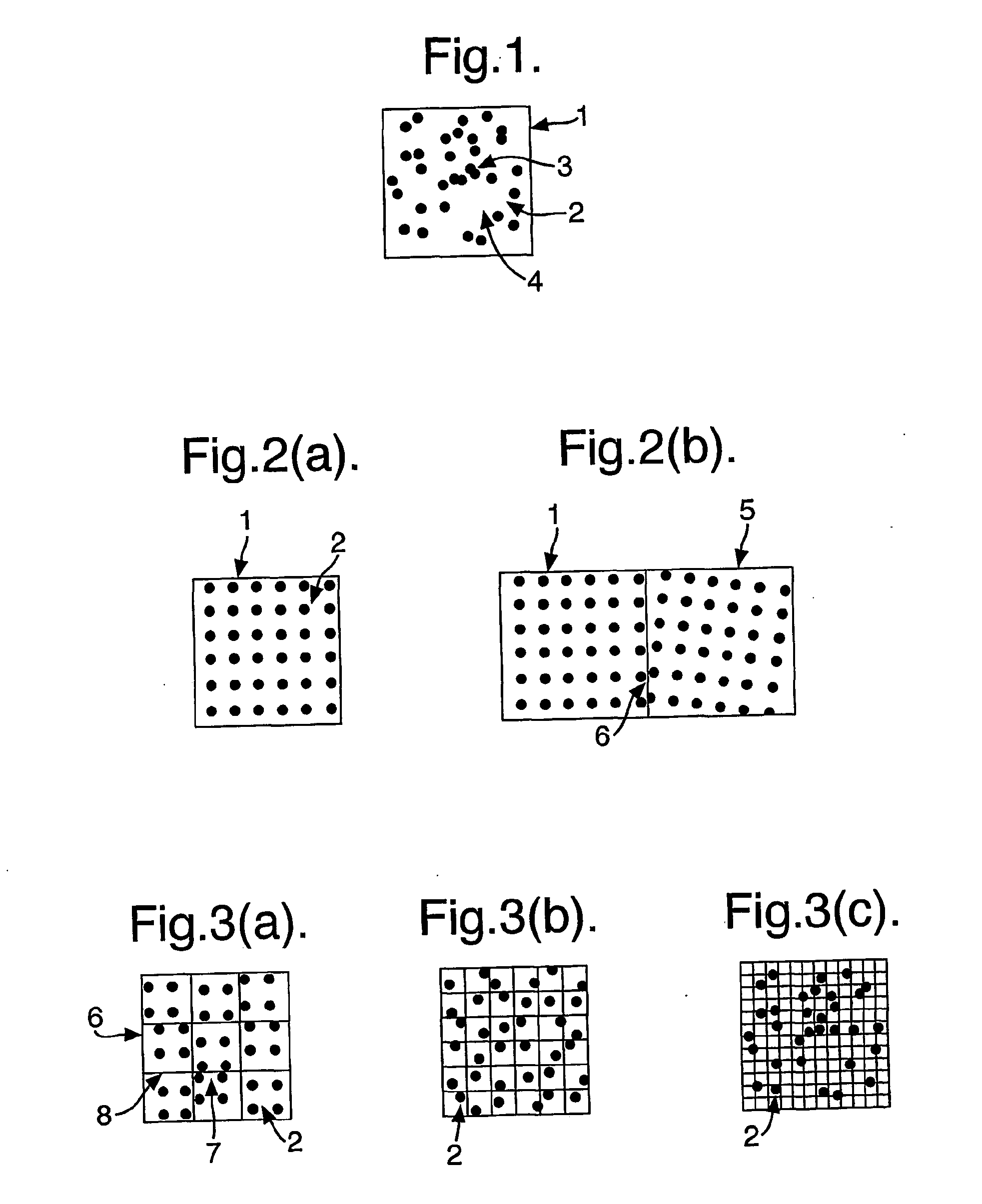
[0033]FIG. 1 shows a single facet 1, as may be used to represent a part of an object, that has been populated with points 2 in a completely random fashion at a point density commensurate with a viewer distance such that in an idealised case the facet appears uniformly opaque. Some apparent clustering of the points can be seen, eg 3, as well as some denuded areas 4. These will show up on the object as an unevenness of brightness of that part of the object. The high density areas will appear to be too bright, and the denuded areas will appear as holes in the object.

[0034]FIG. 2a shows a solution that works over a single facet. The points 2 are arranged in a rectangular mesh that will appear of uniform density if viewed from a sufficient distance. This mesh does not behave so well when neighbouring facets using the same mesh are considered. FIG. 2b shows a typical example of neighbouring facets 1, 5 not lying on the same plane in 3D space that both have a rectangular mesh. In this cas...


PUM


Abstract

A system includes a computer generated hologram (CGH) design plane and a processor capable of representing a three dimensional object. The processor is configured to represent a surface of the three dimensional object by a facet, impose a grid defining a set of nodes upon the facet, and associate object points with each node of the grid. The processor is further configured to orient the facet to include a common global origin in the CGH design plane and displace the object points away from their associated node in a random or pseudo random direction parallel to the CGH design plane.

Description

[0001] This application is a continuation of U.S. application Ser. No. 10 / 415,958, which is a US national phase of international application PCT / GB01 / 04882, filed Nov. 5, 2001 which designates the US. This application claims priority to and incorporates by reference in entirety the following applications: GB0027132.0, filed on Nov. 7, 2000 and U.S. provisional application 60 / 247,048, filed on Nov. 13, 2000.FIELD OF INVENTION [0002] This invention relates to a method of, and system for, representing a three dimensional object for display on a system capable of displaying objects in three dimensions. More specifically, it relates to methods of displaying images comprising of adjoining facets, where each facet is populated, or filled, with points to give the appearance from a distance of a continuous surface. BACKGROUND [0003] In performing the calculations required to display a computer generated hologram (CGH) using an interference based algorithm, it is necessary to populate the obj...

Claims


Application Information

Patent Timeline
Patent Type & Authority Applications(United States)
IPC IPC(8): G06T15/00G03H1/26G03H1/08G06T15/10G06T17/10G06T17/20
CPCG03H1/08G03H1/0808G03H2240/62G03H2210/441G06T17/10G06T17/20G03H2210/30G06T15/10
Inventor CAMERON, COLIN D.COWLING, PETER C.
Owner MIND FUSION LLC
Why Eureka
Try Eureka