

Image recording apparatus and image recording method
a technology of image recording and recording method, which is applied in the field of image recording, can solve the problems of line head, lower production yield, and higher cos
- Summary
- Abstract
- Description
- Claims
- Application Information
AI Technical Summary
Problems solved by technology
Method used
Image

Examples
first embodiment
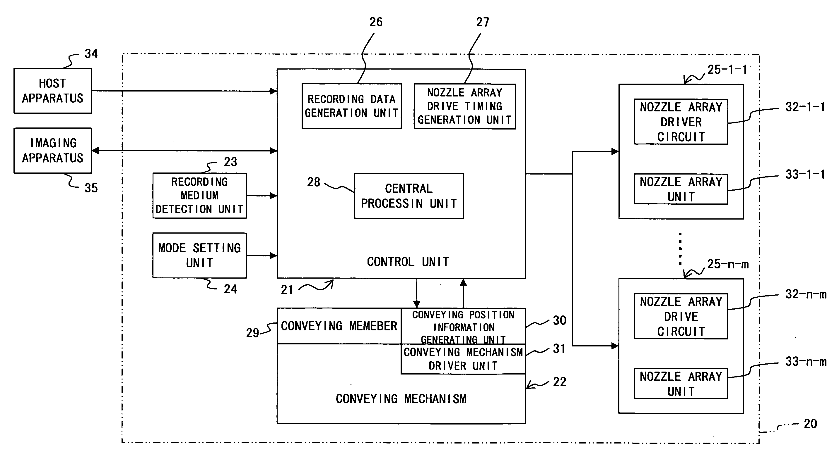
[0103]FIG. 7 is a diagram showing a configuration of a nozzle array drive timing generation unit according to the present invention.
[0104]The nozzle array drive timing generation unit 27 receives an input of an encoder signal of the rotary encoder at the conveying position information generation unit 30, as an input signal as shown in FIG. 7.
[0105]A periodic detection unit 61 counts a prescribed clock pulse during a period of output pulse of the encoder signal, thereby detecting (i.e., measuring) a cycle of the output pulse of the encoder signal. A parameter memory unit 64 stores a timing correction parameter used by the individual record timing correction units 62-1-1 through 62-n-m for correction. The record timing correction units 62-1-1 through 62-n-m and multiplying signal generation units 63-1-1 through 62-n-m are equipped in correspondence with the individual nozzle arrays of the respective nozzle arrays 33-1-1 through 33-n-m. The record timing correction units 62-1-1 through...
second embodiment
[0158]FIG. 12 is a diagram showing a configuration of a nozzle array drive timing generation unit according to the present invention.
[0159]Note that the same component sign is assigned to the constituent component which is common to the above described first embodiment in the description of the present second embodiment and the description here is concentrated on the part different from the first embodiment.
[0160]A nozzle array drive timing generation unit 27 according to the second embodiment of the present invention is configured differently from the nozzle array drive timing generation unit 27 according to the above described first embodiment of the present invention where a conveying position information memory unit 65 is added anew.
[0161]The nozzle array drive timing generation unit 27 according to the second embodiment of the present invention stores a relative move velocity by correlating with the coordinate of the relative move as needed in the conveying position information...
PUM
 Abstract
Description
Claims
Application Information