Parametric joint-coding of audio sources

a technology of audio sources and parametric joints, applied in the field of parametric joint-coding of audio sources, can solve problems such as mono audio signals

Active Publication Date: 2007-12-20
FRAUNHOFER GESELLSCHAFT ZUR FOERDERUNG DER ANGEWANDTEN FORSCHUNG EV
View PDF22 Cites 99 Cited by
  • Summary
  • Abstract
  • Description
  • Claims
  • Application Information

AI Technical Summary

Benefits of technology

The invention proposes a method to decode audio channels with different cues than the original source signals. These cues are either synthesized by a mixer or computed based on the received statistical source information and audio format parameters. These computed cues are then used to control a decoder to produce the output channels. This method allows for a more immersive listening experience and improved spatial sound perception.

Problems solved by technology

The technical problem of this patent text is not specified and requires further analysis and interpretation.

Method used


Image

  • Parametric joint-coding of audio sources
  • Parametric joint-coding of audio sources
  • Parametric joint-coding of audio sources

Examples


Embodiment Construction

II. Definitions, Notation, and Variables

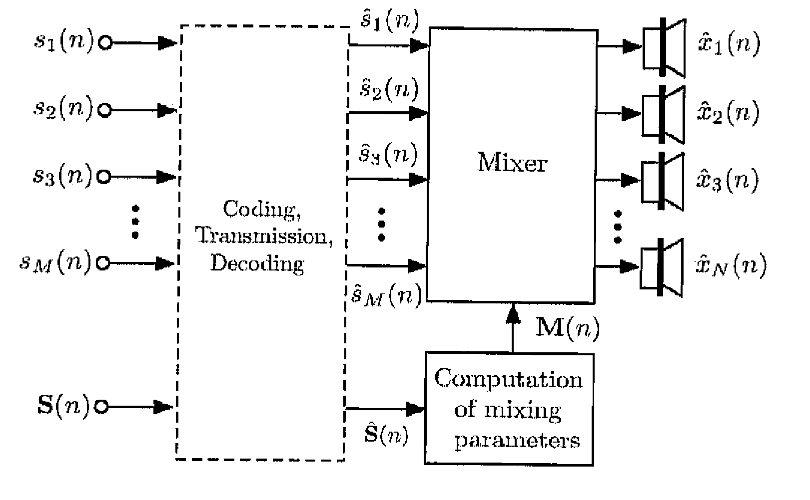
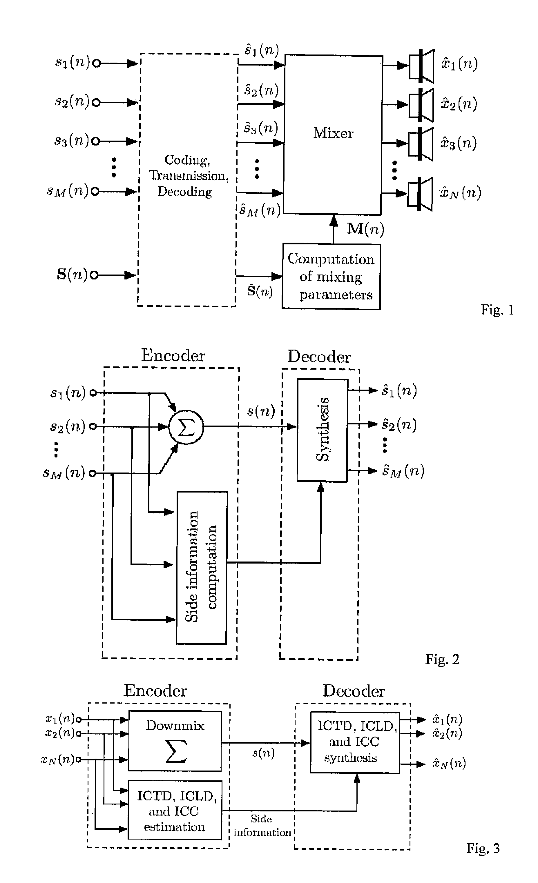
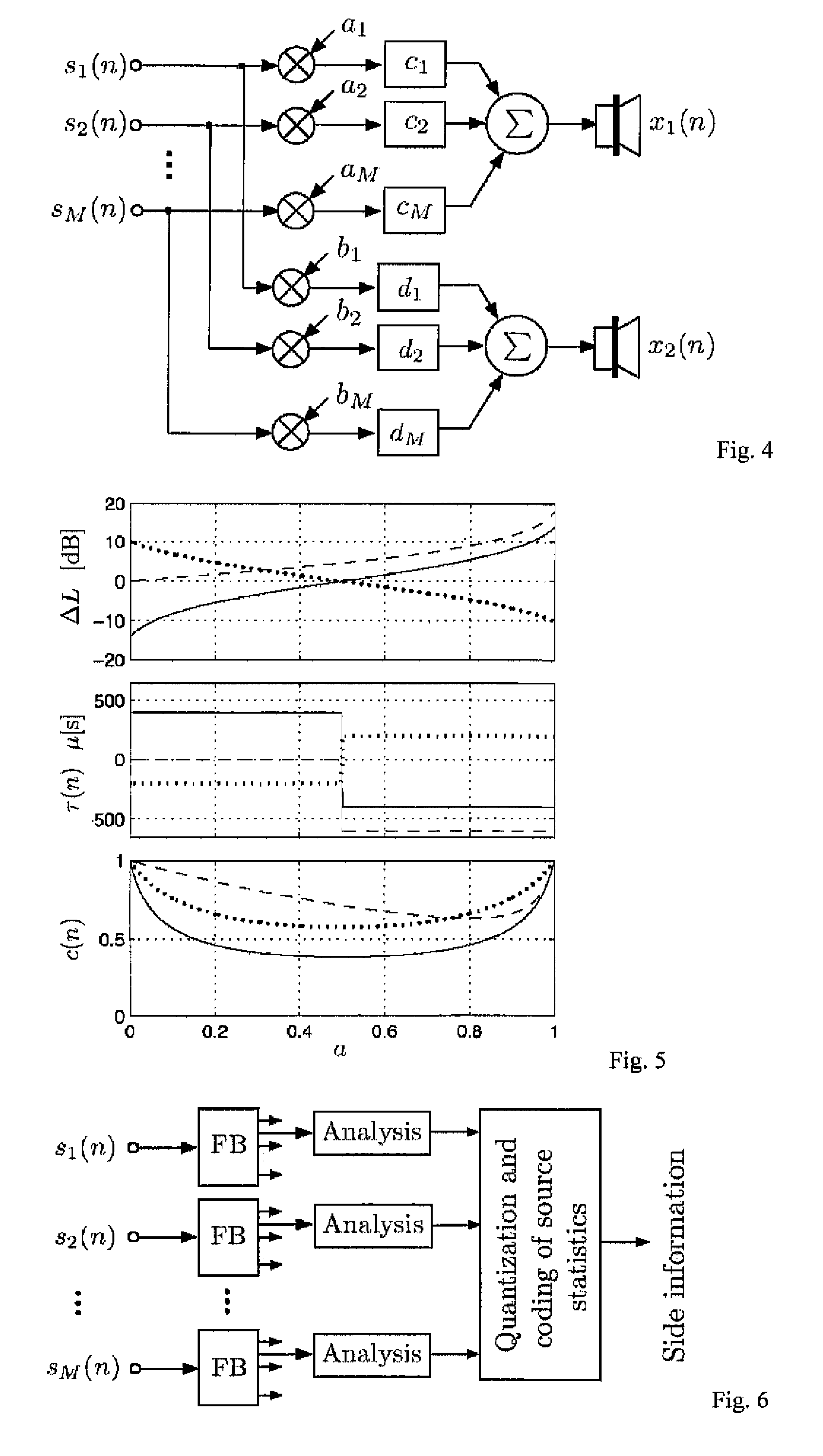
[0027] The following notation and variables are used in this paper: [0028] n time index; [0029] i audio channel or source index; [0030] d delay index; [0031] M number of encoder input source signals; [0032] N number of decoder output channels; [0033] xi(n) mixed original source signals; [0034] {circumflex over (x)}i(n) mixed decoder output signals; [0035] si(n) encoder input source signals; [0036]ŝi(n) transmitted source signals also called pseudo-source signals; [0037] s(n) transmitted sum signal; [0038] yi(n) L-channel audio signal; (audio signal to be re-mixed); [0039] {tilde over (s)}i(k) one subband signal of si(n) (similarly defined for other signals); [0040] E {{tilde over (s)}i2(n)} short-time estimate of {tilde over (s)}i2(n) (similarly defined for other signals); [0041] ICLD inter-channel level difference; [0042] ICTD inter-channel time difference; [0043] ICC inter-channel coherence; [0044]ΔL(n) estimated subband ICLD; [0045]τ(n) est...


PUM


Abstract

The following coding scenario is addressed: A number of audio source signals need to be transmitted or stored for the purpose of mixing wave field synthesis, multi-channel surround, or stereo signals after decoding the source signals. The proposed technique offers significant coding gain when jointly coding the source signals, compared to separately coding them, even when no redundancy is present between the source signals. This is possible by considering statistical properties of the source signals, the properties of mixing techniques, and spatial hearing. The sum of the source signals is transmitted plus the statistical properties of the source signals which mostly determine the perceptually important spatial cues of the final mixed audio channels. Source signals are recovered at the receiver such that their statistical properties approximate the corresponding properties of the original source signals. Subjective evaluations indicate that high audio quality is achieved by the proposed scheme.

Description


Claims


Application Information

Patent Timeline
Owner FRAUNHOFER GESELLSCHAFT ZUR FOERDERUNG DER ANGEWANDTEN FORSCHUNG EV
Why Eureka
Try Eureka