
Apparatus and method for controlling a wave field synthesis renderer means with audio objects

a technology renderer means, applied can solve the problems of affecting the quality of spatial sound reproduction of natural, but also of virtual environments, and wave field synthesis has only rarely been used in the field of wave field synthesis, so as to reduce the sound reproduction quality, increase the efficiency of bit stream, and high flexibility and portability

Active Publication Date: 2008-05-29
FRAUNHOFER GESELLSCHAFT ZUR FOERDERUNG DER ANGEWANDTEN FORSCHUNG EV
View PDF11 Cites 8 Cited by
  • Summary
  • Abstract
  • Description
  • Claims
  • Application Information

AI Technical Summary

Benefits of technology

[0041]The present invention is based on the finding that problems regarding the synchronization on the one hand and problems regarding the lacking flexibility on the other hand can be eliminated by creating, from the scene description on the one hand and the audio data on the other hand, a common output data stream including both the audio files and the position information about the virtual source, wherein the position information for the virtual source is introduced e.g. at headers positioned correspondingly in the data stream in association with the audio files in the output data stream.
[0044]Furthermore, the inventive processing means, which generates the common output data stream from the scene description and the audio files, produces high flexibility and portability to other systems. As a control data stream for the renderer means, a single data stream automatically synchronized in itself, in which the audio data and the position information for each audio object are in fixed association with each other, is created.
[0045]According to the invention, it is guaranteed that the renderer obtains the position information of the audio source as well as the audio data of the audio source in uniquely associated manner, so that no synchronization problems, which would reduce the sound reproduction quality due to “jumping sources”, occur any more.
[0046]Advantageously, the audio and meta data are processed centrally. With this, it is achieved by the inventive processing means that these are transferred together in the data stream corresponding to their temporal reference. Hereby, the bit stream efficiency also is increased, since it is no longer necessary to equip data with time stamps. Furthermore, the inventive concept also provides simplifications for the renderer, the input buffer size of which can be reduced, because it no longer has to hold as much data as if two separate data streams would come.

Problems solved by technology

In previous audio systems, a substantial disadvantage lies in the quality of the spatial sound reproduction of natural, but also of virtual environments.
All usual techniques have the disadvantage that both the site of the loudspeakers and the position of the listener are already impressed on the transmission format.
With wrong arrangement of the loudspeakers with reference to the listener, the audio quality suffers significantly.
Due to this method's enormous demands on computer power and transfer rates, the wave field synthesis has up to now only rarely been employed in practice.
Although the wave field synthesis functions well for environments the properties of which are known, irregularities occur if the property changes or the wave field synthesis is executed on the basis of an environment property not matching the actual property of the environment.
It is assumed that a loudspeaker sends out a sound signal against a wall, the reflection of which is undesired.
But it still suffers from the problem that the central wave field synthesis module, which performs the actual main rendering, i.e. which calculates the individual synthesis signals for the loudspeakers depending on the positions of the virtual sources and depending on the loudspeaker positions, represents a “bottleneck” for the entire system.
If the central rendering unit thus is capable of rendering 32 virtual sources at the same time, for example, i.e. to calculate the synthesis signals for these 32 virtual sources at the same time, serious capacity bottlenecks occur, if more than 32 sources are active at one time in one audio scene.
It is problematic in this system concept that the consistency between scene data and audio data cannot be guaranteed, because these are stored separately from each other and transferred independently of each other to the control / renderer module.
It has turned out that clearly perceivable artifacts may arise due to the fact that the renderer module is still processing audio data of an earlier source arranged from an earlier source position.
With respect to the perceivable sound impression in the reproduction room, this leads to the fact that a source “jumps” from one position to another, which may be very disturbing for the listener, especially if the source was a relatively loud source and if the positions of the two sources considered, i.e. the earlier source and the current source, differ strongly.
A further disadvantage of this concept consists in the fact that the flexibility and / or the portability of the scene description in form of the XML file is low.
Particularly due to the fact that the renderer module comprises two inputs to be tuned to each other, which are intensive to synchronize, application of the same scene description to another system is problematic.
With respect to the synchronization of the two inputs, in order to avoid the described artifacts as far as possible, it is to be pointed out that this is achieved with relatively great effort, namely by employing time stamps or something similar, significantly reducing the bit stream efficiency.
When considering, at this point, that the transmission of the audio data to the renderer and the processing of the audio data by the renderer is problematic anyway due to the enormous data rate needed, it can be seen that a portable interface at this sensitive point is very intensive to realize.

Method used


Image

  • Apparatus and method for controlling a wave field synthesis renderer means with audio objects
  • Apparatus and method for controlling a wave field synthesis renderer means with audio objects
  • Apparatus and method for controlling a wave field synthesis renderer means with audio objects

Examples


Embodiment Construction

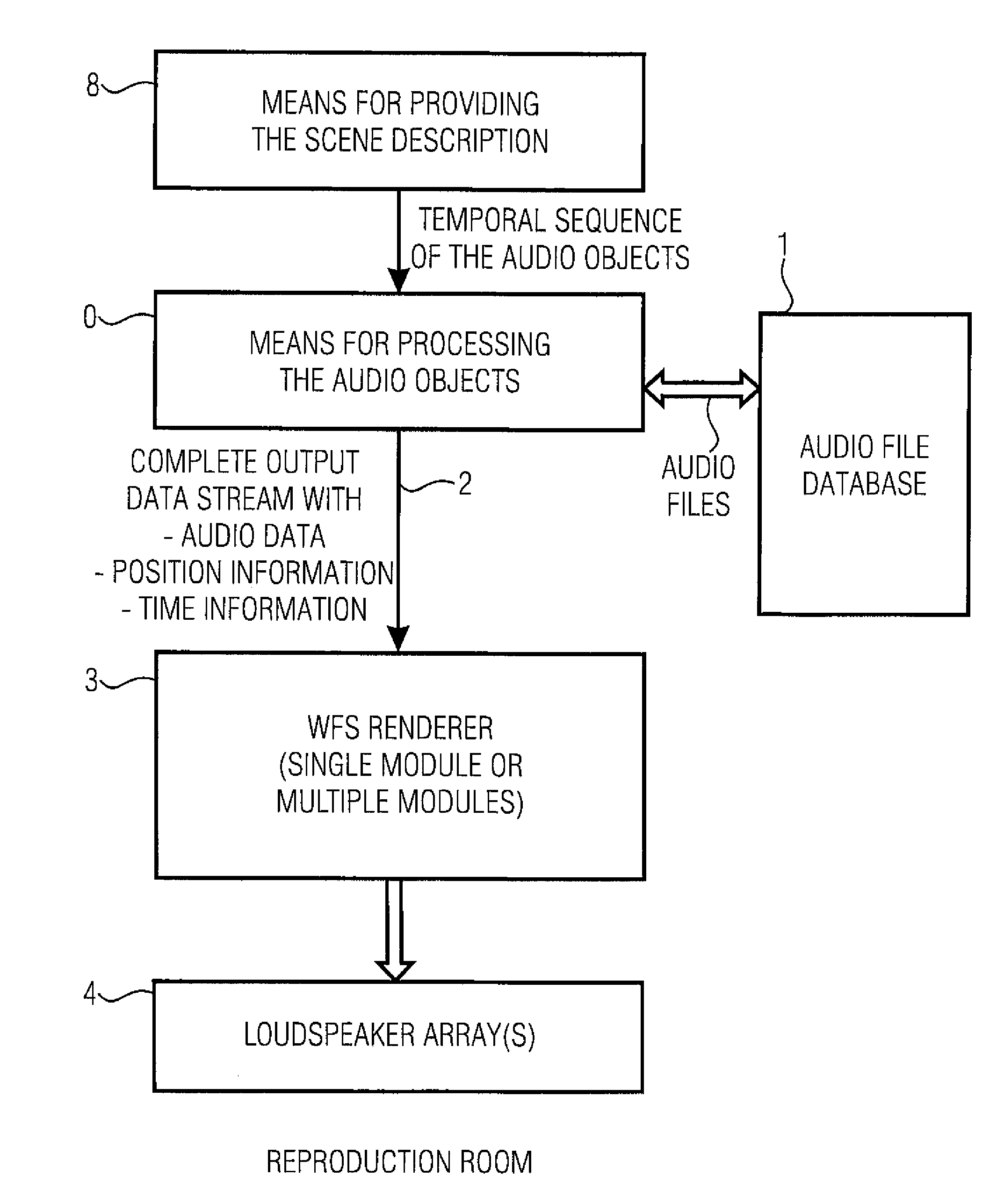
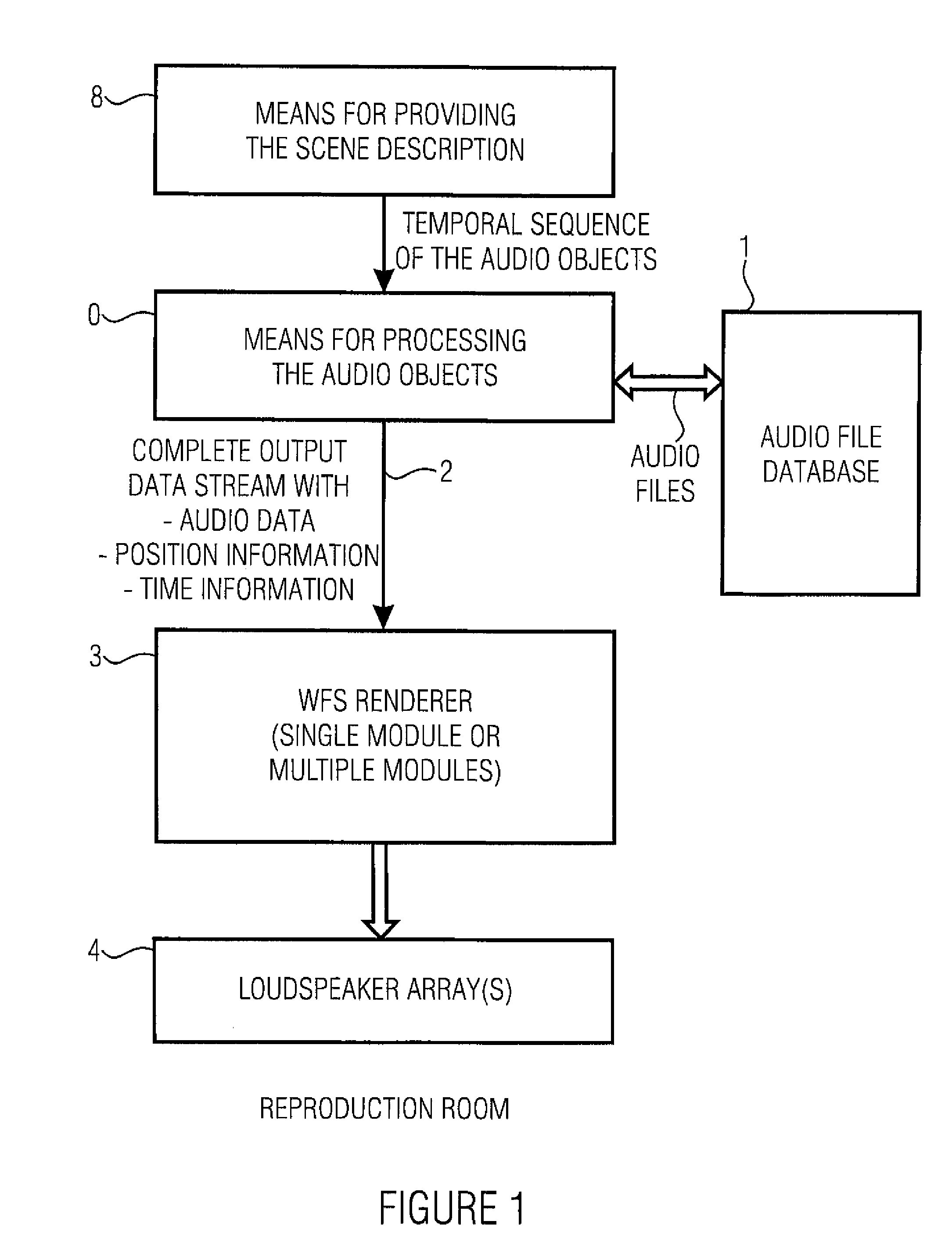
[0059]FIG. 1 shows an apparatus for controlling a wave field synthesis renderer means with audio objects so that the wave field synthesis renderer means generates, from the audio objects, synthesis signals reproducible by a plurality of loudspeakers attachable in a reproduction room. In particular, the inventive apparatus thus includes a means 8 for providing a scene description, wherein the scene description defines a temporal sequence of audio objects in an audio scene, and wherein an audio object includes information on a source position of a virtual source as well as an audio file for the virtual source or reference information referring to the audio file for the virtual source. At least the temporal sequence of the audio objects is supplied to a means 0 for processing the audio objects from the means 8. The inventive apparatus may further include an audio file database 1 by which the audio files are supplied to the means 0 for processing the audio objects.

[0060]The means 0 for ...


PUM


Abstract

An apparatus for controlling a wave field synthesis renderer with audio objects includes a provider for providing a scene description, wherein the scene description defines a temporal sequence of audio objects in an audio scene and further includes information on the source position of a virtual source as well as on a start or an end of the virtual source. Furthermore, the audio object includes at least a reference to an audio file associated with the virtual source. The audio objects are processed by a processor, in order to generate a single output data stream for each renderer module, wherein both information on the position of the virtual source and the audio file itself are included in mutual association in this output data stream. With this, high portability on the one hand and high quality due to secure data consistency on the other hand are achieved.

Description

CROSS-REFERENCE TO RELATED APPLICATIONS[0001]This application is a continuation of copending International Application No. PCT / EP2006 / 001414, filed Feb. 16, 2006, which designated the United States and was not published in English.BACKGROUND OF THE INVENTION[0002]1. Field of the Invention[0003]The present invention relates to the field of wave field synthesis, and particularly to the control of a wave field synthesis rendering means with data to be processed.[0004]The present invention relates to wave field synthesis concepts, and particularly to an efficient wave field synthesis concept in connection with a multi-renderer system.[0005]2. Description of the Related Art[0006]There is an increasing need for new technologies and innovative products in the area of entertainment electronics. It is an important prerequisite for the success of new multimedia systems to offer optimal functionalities or capabilities. This is achieved by the employment of digital technologies and, in particul...

Claims


Application Information

Patent Timeline
Patent Type & Authority Applications(United States)
IPC IPC(8): H04S3/00
CPCH04S3/008H04S2420/13H04S7/30
Inventor REICHELT, KATRINGATZSCHE, GABRIELBRIX, SANDRA
Owner FRAUNHOFER GESELLSCHAFT ZUR FOERDERUNG DER ANGEWANDTEN FORSCHUNG EV
Learn More