Insulated concrete form

a concrete form and insulation technology, applied in the field of wall forming structure, can solve the problems of increasing labor costs and remaining numerous problems to solv

Active Publication Date: 2007-12-27
ENCON ENVIRONMENTAL CONSTR SOLUTIONS
View PDF54 Cites 33 Cited by
  • Summary
  • Abstract
  • Description
  • Claims
  • Application Information

AI Technical Summary

Benefits of technology

[0005] The insulated concrete form of the present invention is intended to obviate

Problems solved by technology

Either method when used in combination with traditional wooden forms is time consuming which increas

Method used


Image

  • Insulated concrete form
  • Insulated concrete form
  • Insulated concrete form

Examples


Embodiment Construction

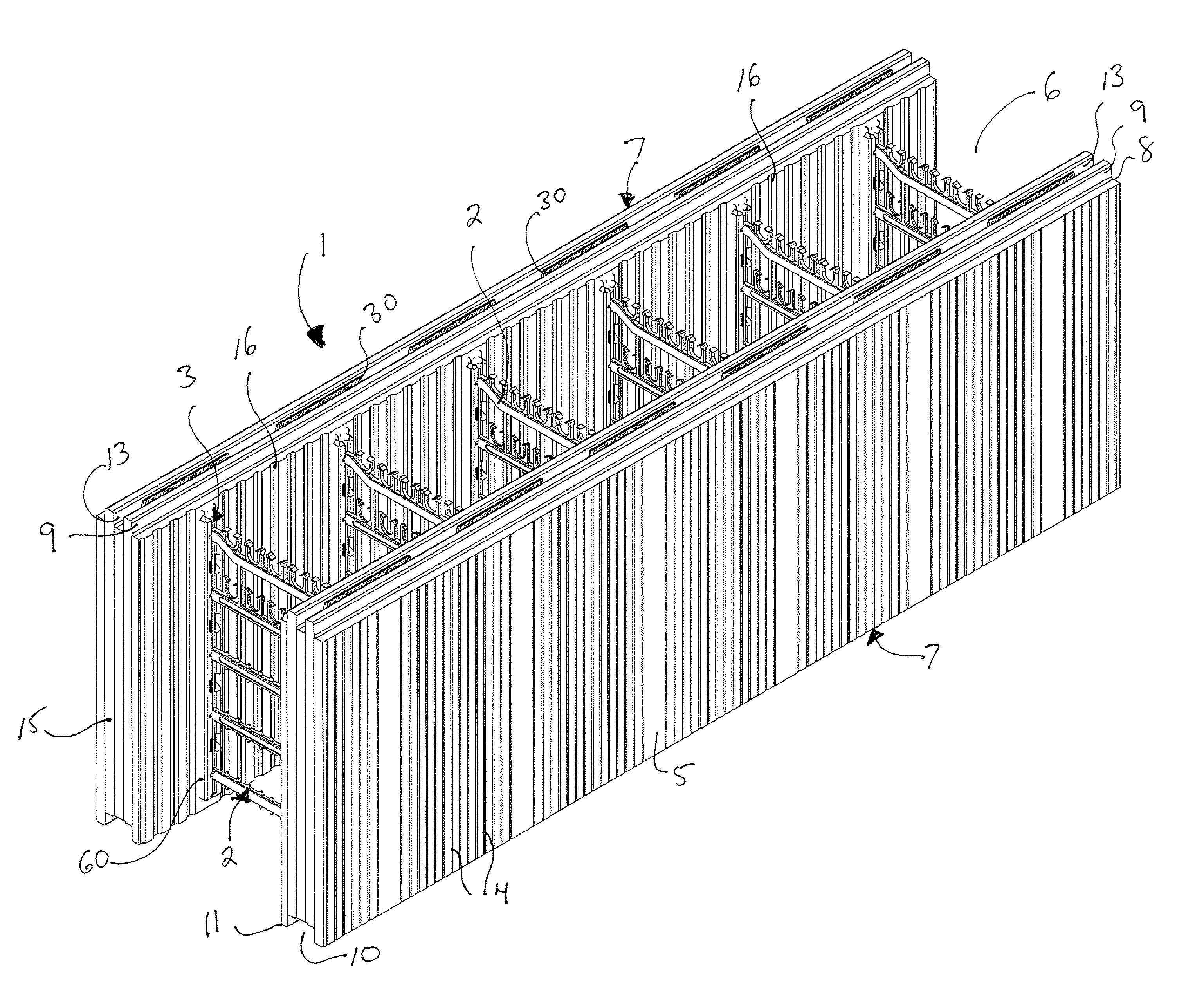
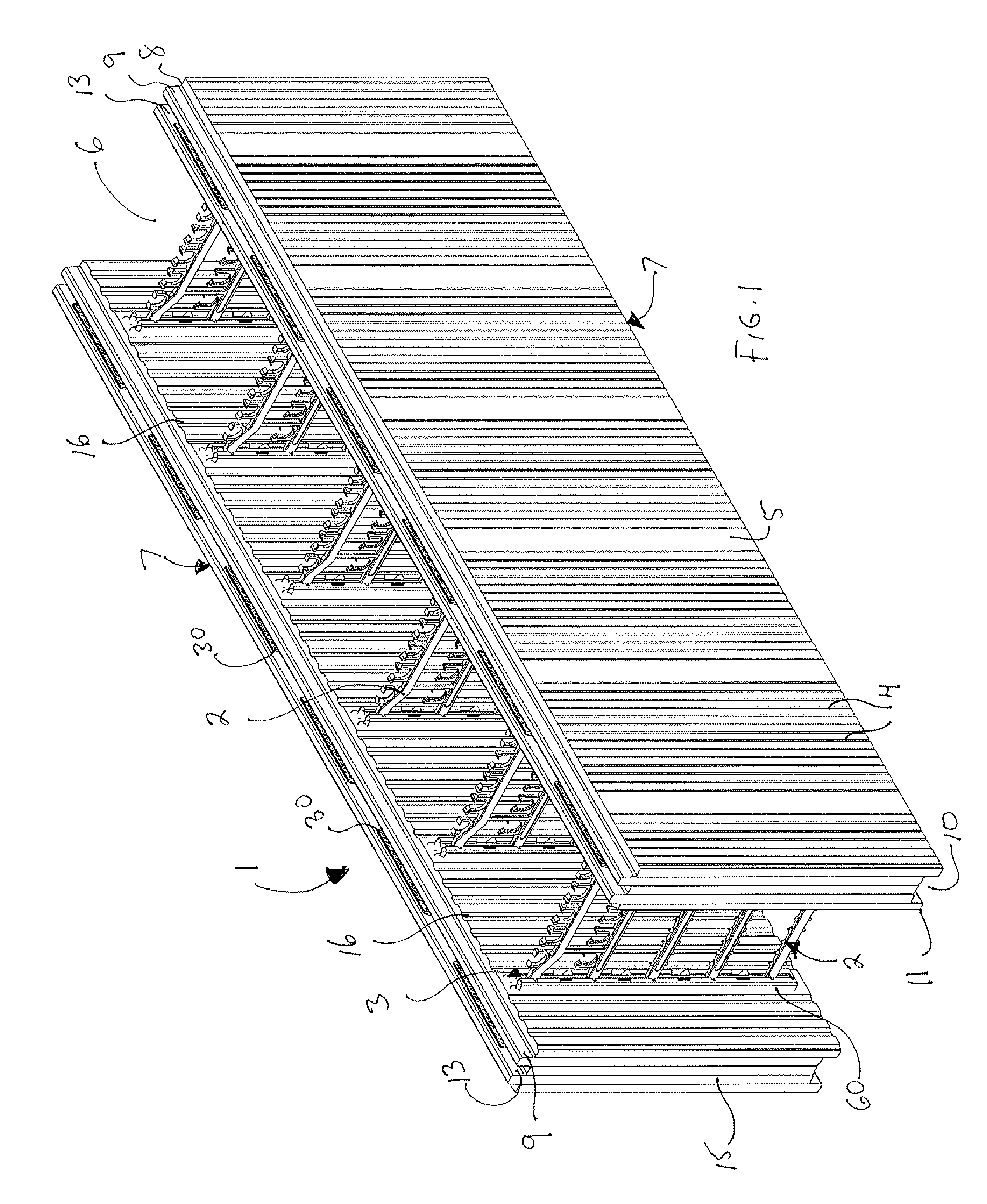
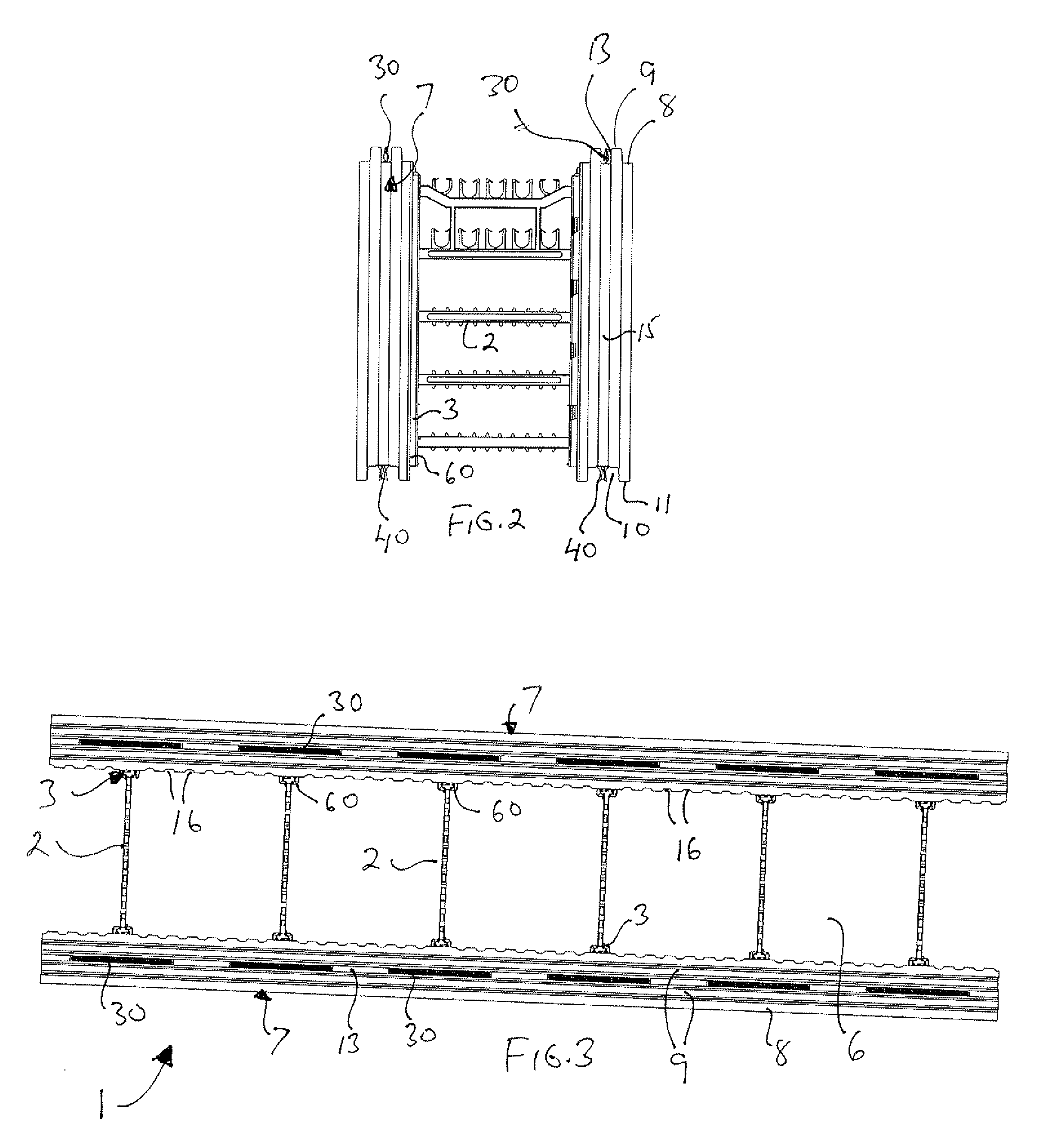
[0043] Referring initially to FIG. 1, there is shown a single discrete straight ICF block 1 which is the basic building unit of the present ICF system. These blocks will typically be 48 inches in length and 16 inches high although these dimensions can be varied up or down depending on job requirements. These blocks are placed end to end for the length of the wall and are stacked vertically, typically in a brick or staggered pattern, for the wall's height. The width of the block will vary with the width of the concrete wall being formed, which typically will vary from 4 inches to 10 inches of concrete in thickness. Each block consists of opposed spaced apart panels 7 of a moldable insulating material in the nature of a plastic foam such as expanded polystyrene, known as EPS, which is formed into rigid slabs that provide strength and rigidity as is known in the art. The specification of EPS is by example only, and the use of other insulating foam materials is contemplated within the s...


PUM


Abstract

There is described an apparatus for a concrete form for an insulated wall. The apparatus comprises first and second wall panels arranged in opposed spaced apart parallel relationship, each panel having an inner surface, an outer surface, an upper edge surface, a lower edge surface and end surfaces. A plurality of retainers are secured within each of said first and second panels at spaced apart intervals, each retainer including a connecting portion extending outwardly from the inner surface of each panel, and an anchoring portion. The anchoring portion includes a framework disposed within the panels, an upper connector extending upwardly from each panel's upper edge surface and a lower connector extending downwardly from each panel's lower edge surface. The upper and lower connectors are adapted to respectively engage the upper and lower connectors of the next vertically adjacent panel to securely attach the panels together. A plurality of cross webs extends between the first and second panels to tie them together, the cross webs being adapted for respective connection to the connecting portions of opposed retainers in the first and second panels.

Description

FIELD OF THE INVENTION [0001] The present invention relates to a wall forming structure and to particularly to an insulated concrete form (ICF) system and apparatus. BACKGROUND TO THE INVENTION [0002] Traditionally, concrete walls have been poured between braced wooden forms. Once the forms are removed, the walls are separately insulated either by means of insulation batts placed between wooden studs or using panels of foam insulation, typically expanded polystyrene (EPS) panels adhered to the walls in ways known in the art. Finishing surfaces are then attached either to the wooden studs or to the EPS panels. Either method when used in combination with traditional wooden forms is time consuming which increases labour costs. [0003] In response, the industry has developed insulated concrete forms which themselves are the forms used for concrete walls (usually foundation walls) that remain in place after the concrete has cured. The ICFs provide both thermal and acoustical insulation, a...

Claims


Application Information

Patent Timeline
IPC IPC(8): E04C1/41
CPCE02D27/02E04B2002/8694E04B2002/867E04B2/8635
Inventor MARSHALL, DALEYEUNG, TONYGALASSO, CARLO
Owner ENCON ENVIRONMENTAL CONSTR SOLUTIONS
Why Eureka
Try Eureka