
Composite Lever and Method of Making Same

Inactive Publication Date: 2007-12-27
SACOMA INT
View PDF3 Cites 1 Cited by
  • Summary
  • Abstract
  • Description
  • Claims
  • Application Information

AI Technical Summary

Benefits of technology

[0008]One object of the present invention is to provide a lever that is significantly less costly to manufacture, but which has the required strength for mechanical outputs.

Problems solved by technology

Existing transmission selector levers are expensive machined assemblies requiring a solid shaft to provide the appropriate bending strength and a drilled hole extending through a substantial portion of the shaft.
Replacing the shaft with a thick-walled tubing to achieve the deflection strength reduces cost but is still costly because thick-walled tubing is expensive to make.
The use of these shafts is more problematic when the shaft must be bent, frequently in multiple places, to accommodate functional and operator ergonomic requirements.
Although this may simplify the manufacturing process when dealing with complex multiple bends and complex shapes, it does not have the requisite strength necessary to provide force input for devices like those used in transmissions.

Method used


Image

  • Composite Lever and Method of Making Same
  • Composite Lever and Method of Making Same
  • Composite Lever and Method of Making Same

Examples


Embodiment Construction

[0018]For the purposes of promoting an understanding of the principles of the invention, reference will now be made to the embodiments illustrated in the drawings and specific language will be used to describe the same. It will nevertheless be understood that no limitation of the scope of the invention is thereby intended, such alterations and further modifications in the illustrated device, and such further applications of the principles of the invention as illustrated therein being contemplated as would normally occur to one skilled in the art to which the invention relates.

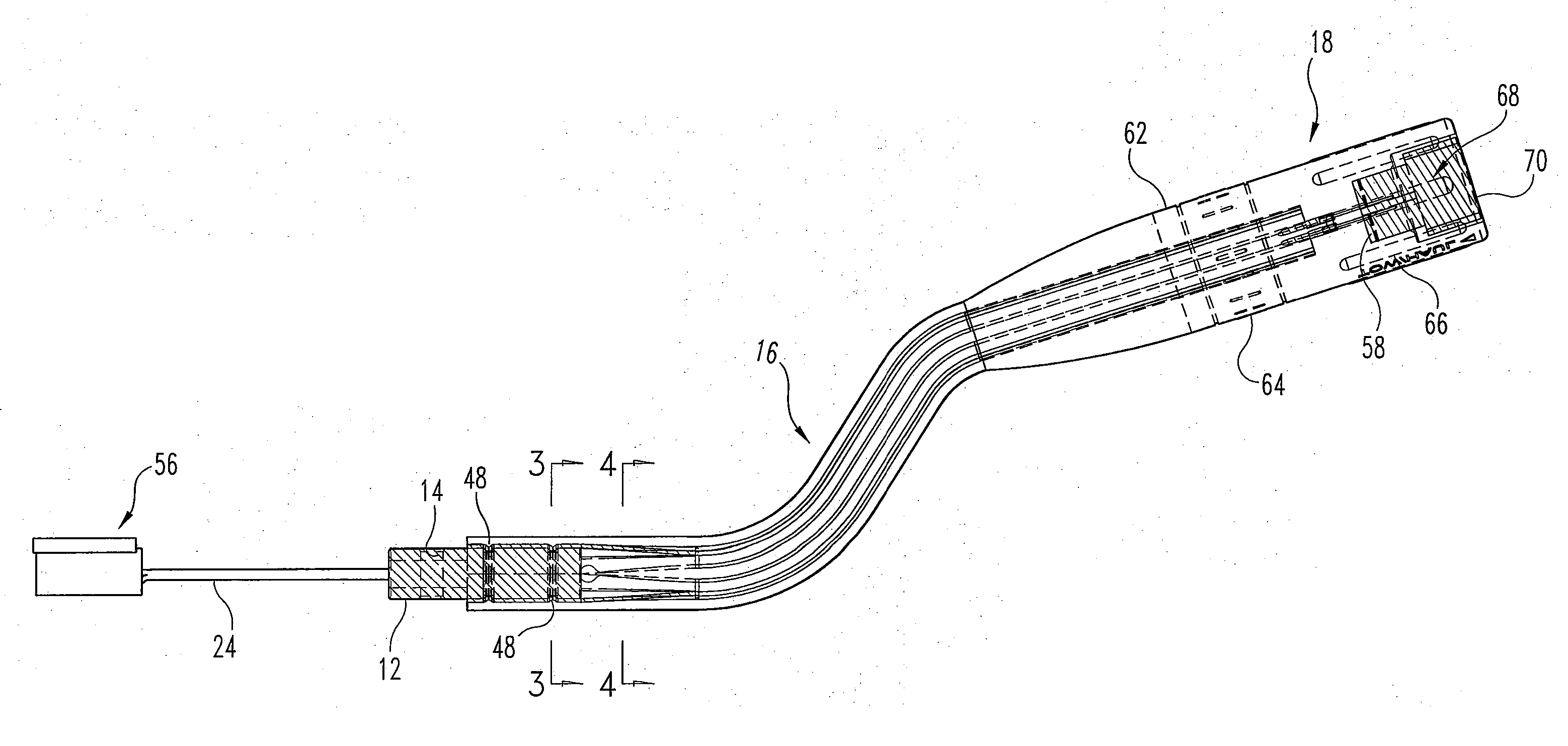
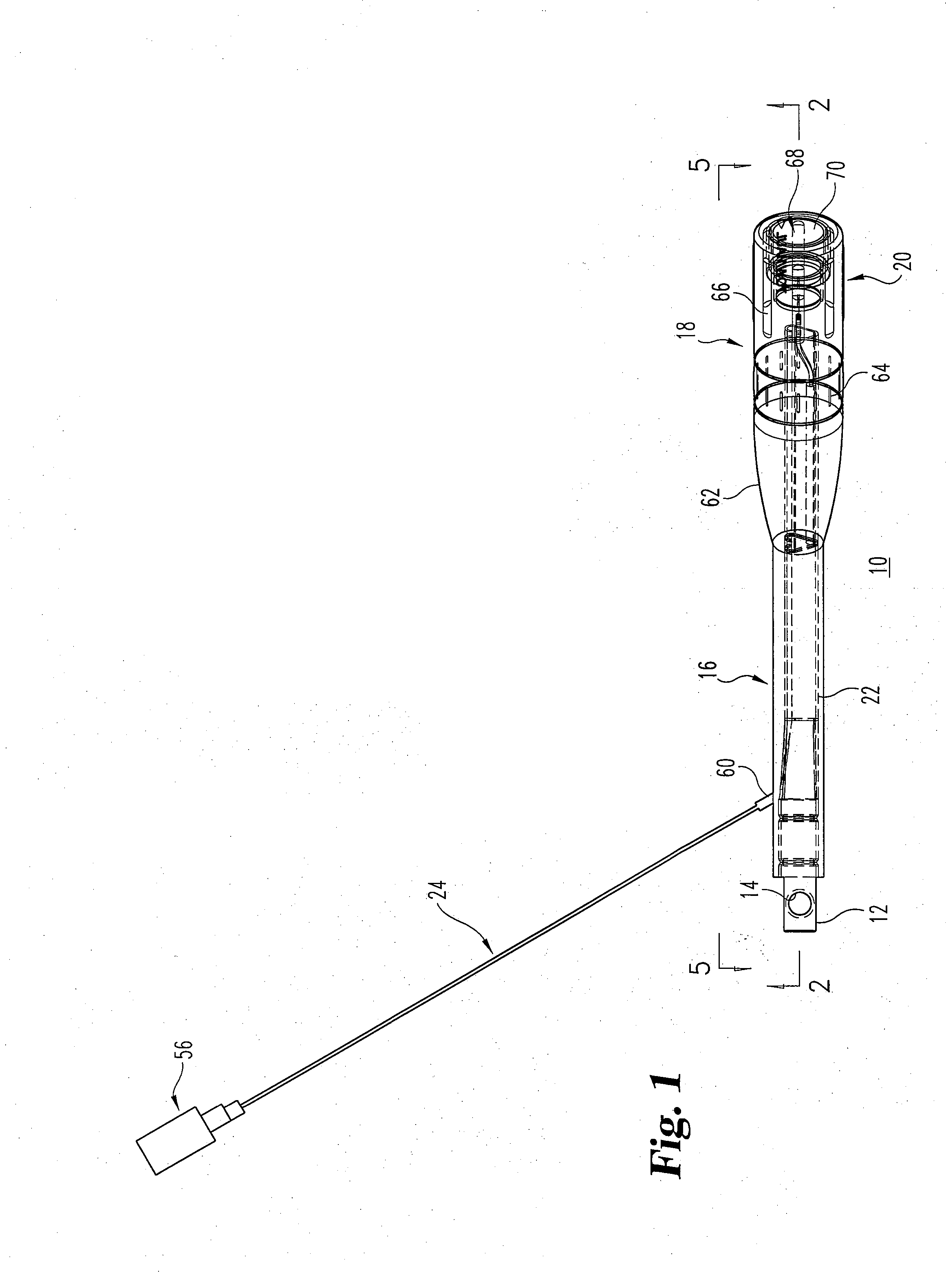
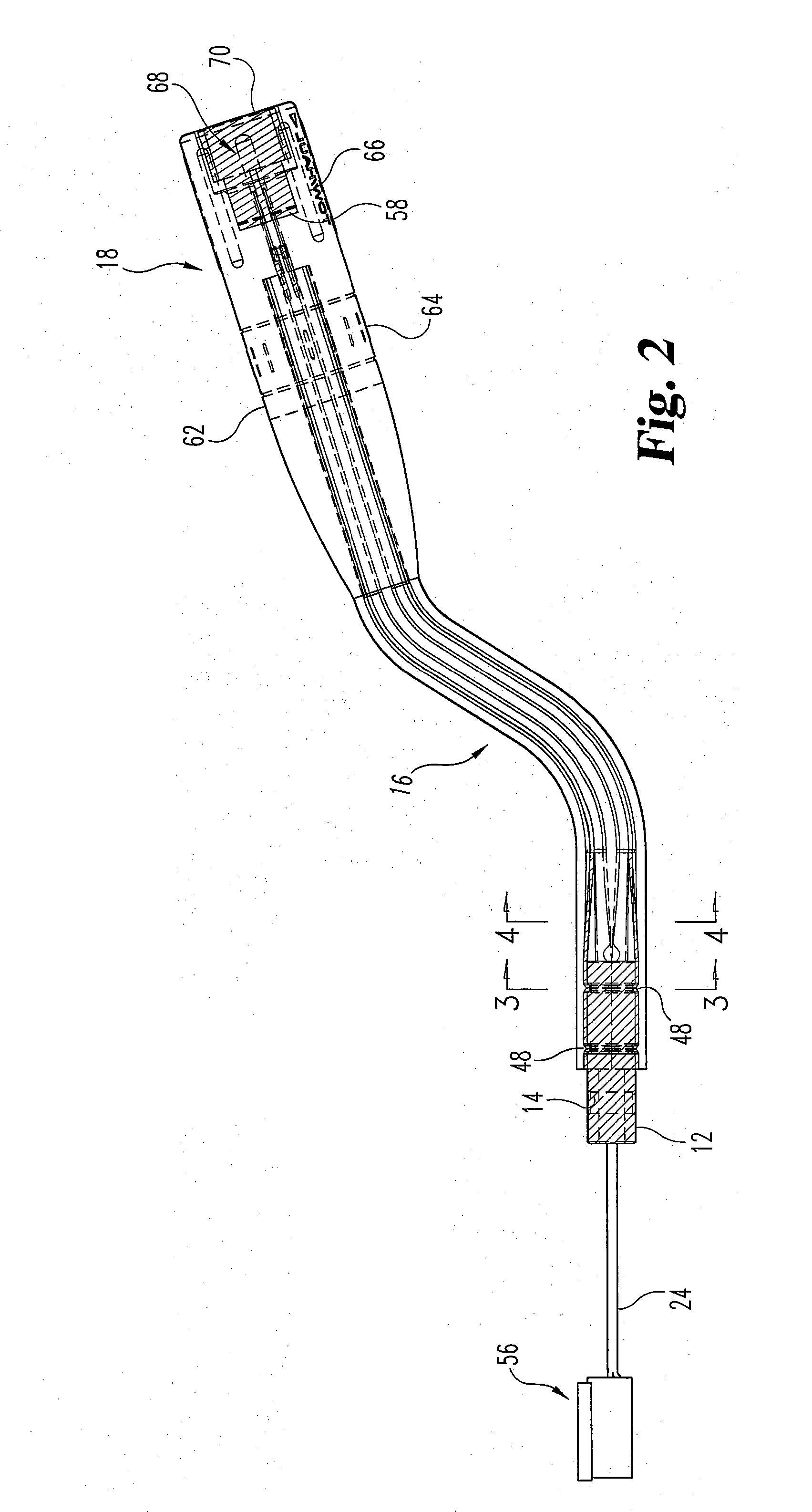
[0019]FIG. 1 shows a lever generally indicated by reference character 10. Lever 10, by way of example, is used as a transmission selector lever. However, it could be employed for any one of a multitude of functions providing a mechanical output. Lever 10 comprises a base 12 shown herein as cylindrical and having a through hole 14 for appropriate connection to a transmission selector mechanism. Lever 10 has a sh...


PUM


Abstract

The present invention is a composite transmission selector lever that avoids the multiple manufacturing steps of current levers and in addition gives a significant reduction in cost. The lever comprises an open-sided, elongated stamped, sheet steel element having a triangular cross section shape with the open end of the triangle curved inwardly. The triangular shape is to provide the maximum bending strength to the resultant structure. One end of the mechanism is crimped and / or welded to fasten over the circular section of a base and the other end is formed to extend to an operator handle. A wire for a switch in the handle is laid through the open side of the element and the composite assembly is overmolded with a high strength thermoplastic material, such as polyamide 6, having a surface finish suitable for an as-molded condition. The molding material substantially encloses the interior of the open-sided element, thus securing the electrically conductive wire in place and providing a significant contribution to the overall bending strength of the assembly.

Description

BACKGROUND OF THE INVENTION[0001]The present invention relates to levers and more specifically to improvements in how such levers are made.[0002]Over the centuries, levers have been an essential part of any activity in which mechanical devices are controlled, actuated, manipulated, and the like. Usually, a lever consists of a base connecting to some part of the machinery, such as a linkage, a shaft which is either straight or bent according to the application and an operator handle to enable ergonometric and efficient grasping of the lever to induce the proper movement. The lever can be movement through an arc in a single plane or multiple planes, as in a gear shift. In some cases, the lever could even be rotated about its axis for further mechanical output. In recent years, there are many instances in which a lever providing a mechanical output must also provide an electrical output, usually by some form of switch. Levers of this type are most commonly found in the automotive field...

Claims


Application Information

Patent Timeline
IPC IPC(8): G05G1/04
CPCG05G1/04Y10T74/20582G05G1/503
Inventor SEIM, GERALD W.SEIM, KENNETH J.
Owner SACOMA INT
Learn More