
Electronically controlled converter clutch for an automatic transmission

a technology of automatic transmission and converter clutch, which is applied in the direction of rotary clutches, fluid couplings, gearing, etc., can solve the problems of inefficiency of torque transmission through the torque converter and impair fuel economy, and achieve the effect of smoother operation

Active Publication Date: 2007-12-27
GM GLOBAL TECH OPERATIONS LLC
View PDF6 Cites 18 Cited by
  • Summary
  • Abstract
  • Description
  • Claims
  • Application Information

AI Technical Summary

Benefits of technology

[0006]The apparatus may also include an isolator configured to at least partially absorb engine torque spikes and thereby provide smoother operation.
[0010]The isolator may be disposed downstream from the turbine such that any turbine inertia spikes are at least partially absorbed thereby providing smoother operation.

Problems solved by technology

However, at higher torque converter speed ratios, the transfer of torque through the torque converter becomes inefficient and impairs fuel economy.

Method used


Image

  • Electronically controlled converter clutch for an automatic transmission
  • Electronically controlled converter clutch for an automatic transmission
  • Electronically controlled converter clutch for an automatic transmission

Examples


Embodiment Construction

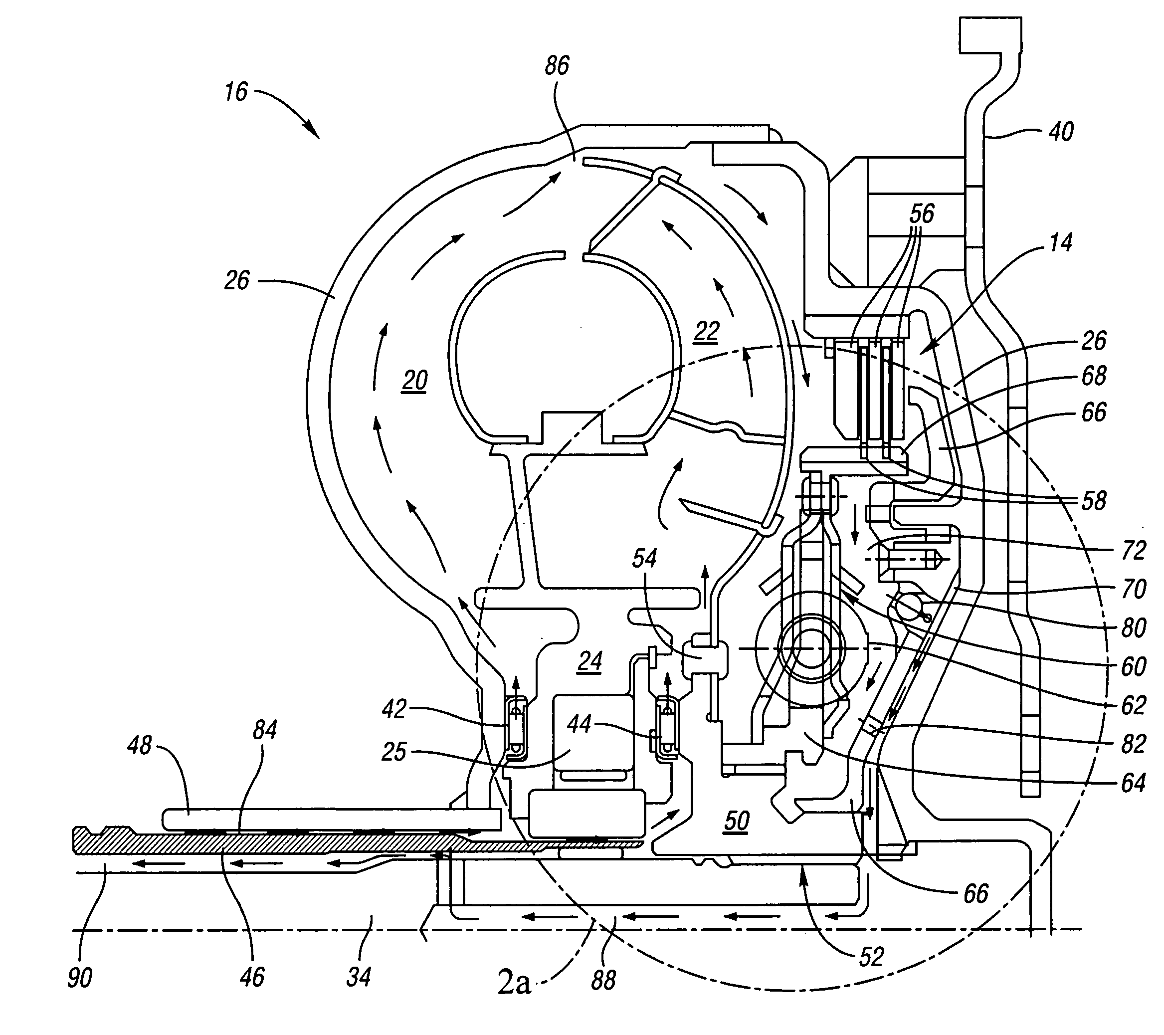
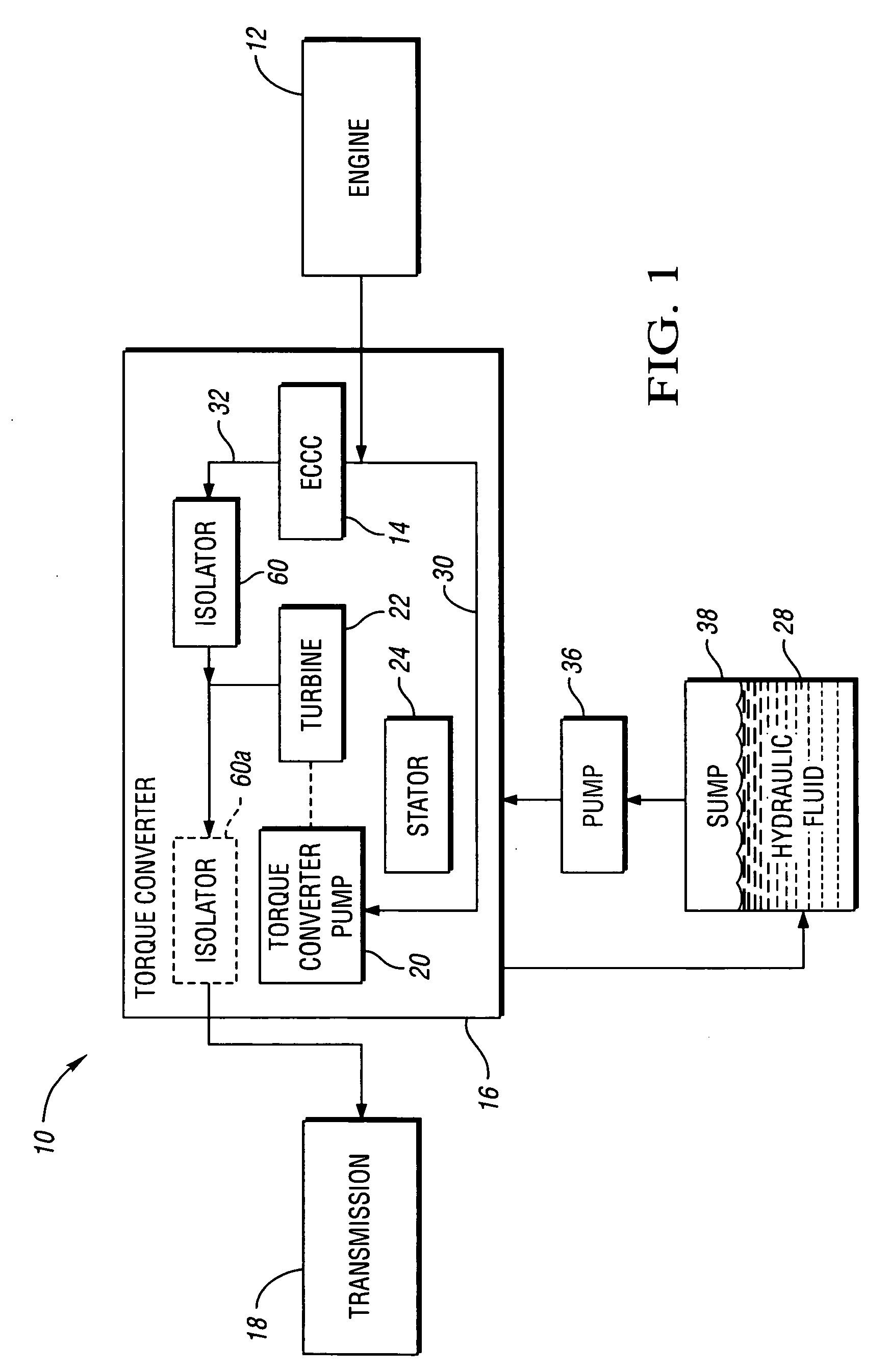
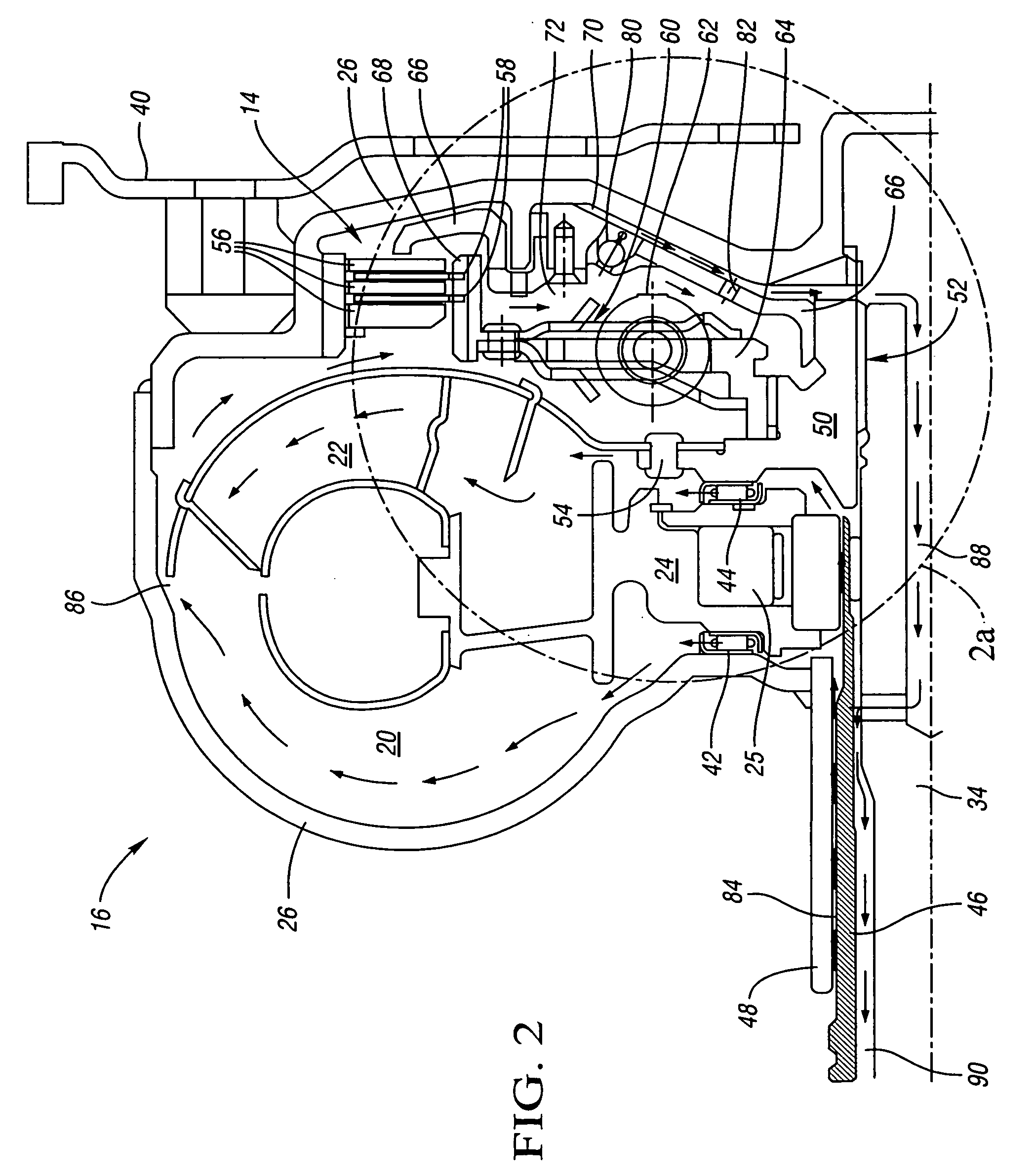
[0019]Referring to the drawings, wherein like reference numbers refer to like components, FIG. 1 shows a schematic depiction of a vehicle 10 in accordance with the present invention. The vehicle 10 includes an engine 12, a torque converter 16, and a transmission 18. The torque converter 16 includes an electronically controlled converter clutch (hereinafter ECCC) 14, a torque converter pump 20 (a driving member), a turbine 22 (a driven member), and a stator 24. The torque converter 16 further includes a housing member 26 (shown in FIG. 2) attached to the torque converter pump 20 such that a chamber full of hydraulic fluid 28 is formed therebetween.

[0020]According to the preferred embodiment of the present invention, the torque converter 16 includes an isolator 60 positioned as shown. According to an alternate embodiment described in detail hereinafter with respect to FIG. 2a, the isolator 60a may be relocated as shown by the dashed line representation thereof. It should therefore be ...


PUM


Abstract

The apparatus of the present invention provides a torque converter for an automatic transmission. The torque converter includes an electronically controlled converter clutch disposed within a torque converter housing. A release passage in fluid communication with the electronically controlled converter clutch is defined between standard functional torque converter components. The release passage is configured to transfer hydraulic fluid to release the electronically controlled converter clutch. An apply passage in fluid communication with the electronically controlled converter clutch is also defined between standard functional torque converter components. The apply passage is configured to transfer hydraulic fluid to engage the electronically controlled converter clutch. The electronically controlled converter clutch is characterized by the absence of a dedicated hydraulic supply line

Description

TECHNICAL FIELD[0001]The present invention pertains generally to an electronically controlled converter clutch and a method of operation.BACKGROUND OF THE INVENTION[0002]A torque converter is a hydrodynamic unit that transfers torque between an engine and an automatic transmission. The torque converter generally includes a torque converter pump (driving member), a turbine (a driven member), and a stator that are disposed in a housing full of hydraulic fluid. The torque converter pump is generally disposed at a rear portion of the housing (away from the engine), and it turns with a crankshaft of an engine. The turbine is generally disposed at a front portion of the housing (near the engine), and is connected to a transmission input shaft. The turbine is free to rotate independently from the torque converter pump.[0003]The hydraulic fluid flows from the torque converter pump toward the turbine in a radial outer portion of the torque converter. The hydraulic fluid then flows from the t...

Claims


Application Information

Patent Timeline
Patent Type & Authority Applications(United States)
IPC IPC(8): F16H45/02
CPCF16H45/02F16H2045/0284F16H2045/021F16H61/143
Inventor SAMIE, FARZADCARLSON, RICHARD W.BARTOS, ANDREW L.
Owner GM GLOBAL TECH OPERATIONS LLC
Learn More