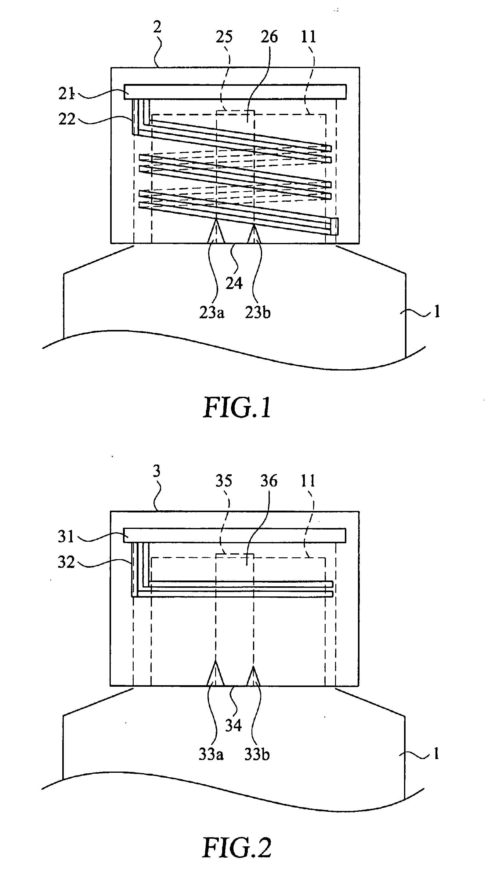
[0031]With reference to the drawings and in particular to FIG. 1, FIG. 1 is a schematic side view showing a closure incorporated with a sealing detection mechanism using RFID tag constructed in accordance with a first embodiment of the present invention. A container 1 is used for the accommodation of substances that may be in liquid form or solid form and has a top open end 11 to be closed by a closure 2. The container 1 may be made of any rigid materials like glasses, plastics, or metal. The closure 2 is provided with a fastening structure and may be fastened by any conventional way to the container 1 or removed from the container 1. The closure 2 may be made of any materials that enable the tight sealing of the closure 2 to the container 1.
[0032]The closure 2 is incorporated with a sealing detection mechanism of the present invention. The sealing detection mechanism comprises a RFID tag 21 arranged at a predetermined position at the closure 2 and a plurality of conductive units 22 extending from the RFID tag 21. For example, the RFID tag 21 is mounted to an internal space at the bottom surface of the top plate of the closure 2. The RFID tag 21 stores the information of the product, e.g. the sealing condition, the price, the expiration date, product number and so on. The RFID tag 21 may be a known active RFID tag or a passive RFID tag. Preferably, passive RFID tag is used, which is cheaper in cost and does not require any power supply.
[0033]The conductive units 22 are parallelly arranged and spaced from each other with a predetermined distance. The conductive units 22 may be arranged at any part of the closure 2. In the first embodiment, the conductive units 22 are embedded in the closure 2. The number of conductive units 22 used depends on the precision requirement in practice. As shown in FIG. 1, the conductive units 22 have a helical structure extending spirally downward from the RFID tag 21 and surrounding on an inner wall surface of the closure 2. The conductive units 22 may be made of pliable electrically conductive material. Preferably, the conductive units 22 are made of metallic materials such as aluminum, copper, alloy, or transparent conducting glue.
[0034]The sealing detection mechanism also includes other electrical components (not shown). Each of the conductive units 22 is connected with the electrical components to form a conductive circuit loop. Hence, the number of conductive circuit loops formed is equal to the number of the conductive units 22. When the RFID tag 21 and the conductive unit 22 are properly connected, the conducting circuit loop is in a closed state, and a conductive code is generated. When the conducting circuit loop is in an open state, resulting from the fracture of the conductive unit 22, an open-circuit code is generated. Both the conductive codes and the open-circuit codes are detected by the RFID tag 21.
[0035]In the case that an electrically conductive closure, e.g. a metallic closure, is used, it is needed to insert an electrically insulating layer to electrically separate the conductive units 22 and the closure 2.
[0036]The closure 2 is provided with an operable tear portion including two inverted V-shaped notches 23a, 23b at the bottom edge of closure 2. The bottom edge between the two V-shaped notches 23a, 23b forms a tear tab 24 that facilitates the user to pull. Moreover, the operable tear portion includes at least a tear line. For example, the wall of the closure 2 is preferably formed with a tear line 25 which has a substantially thinner wall thickness and can be easily broken upon acting of force. The tear line 25 extends from one V-shaped notch 23a vertically up to the upper section of the closure 2 and then extends horizontally for a predetermined distance. Finally, the tear line 25 extends downward to the other V-shaped notch 23b. The longitudinal part surrounded by the tear line 25 forms an easy tear strip 26. Upon the pulling of the tear tab 24 by the user, the tear strip 26 is easily torn along the tear line 25. Thereby, the user can remove the tear strip 26 completely and then open the closure 2 from the container 1 to reveal the contents of the container 1 or to obtain the substances in the container 1.
[0037]It can be seen from the drawing that the tear line 25 extends across the conductive units 22, but the tear line 25 does not extend across the RFID tag 21. When the tear strip 26 is torn, the conductive units 22 are simultaneously broken. In some situations, the conductive units 22 may be partially damaged when only a part of the tear strip 26 is pulled by an external force, while in some situations, the conductive units 22 may be completely damaged when the tear strip 26 is wholly removed. The degree of the damage of the conductive units 22 indicates the degree of unsealing of the closure 2.
[0038]When the closure 2 is not properly sealed or when the closure 2 is damaged, one or more conductive units are broken, and these damaged conducting circuit loops become open state. Each of the damaged conducting circuit loops generates an open-circuit code. Both the conductive codes and the open-circuit codes are detected by the RFID tag 21. A signal is generated at the RFID tag 21, which represents the sealing condition of the closure 2. A RFID reader can detect the sealing condition of the closure 2 by reading the signal transmitted from the RFID tag 21.
[0039]In practice, multiple ways of encoding the conductive code and the open-circuit code may be adopted. For example, the conductive code (generated when the conducting circuit loop is in a closed state) may be a “0” in the binary code system, while the open-circuit (generated when the conducting circuit loop is in an open state) may be a “1”. For a sealing detection mechanism provided with multiple numbers of codes, e.g. four codes, a signal of “0000’ represents a perfectly sealed product, while a signal of “1111” represents an opened product. Each “1” represents a flaw of the sealing. From the position of the “1”, the inspector can find out the locations of the damages at the sealing.
[0040]The helical shaped conductive units 22 are sensitive and precise in revealing the sealing condition of a product. It is noted that, the tear off of the tear strip 26 would damage the conductive units 22, but it would not damage the RFID tag 21. In other words, the RFID tag 21 is still effective in providing the product information to the RFID reader and for tracking of the product even though the sealing is broken.
[0041]Please refer to FIG. 2. FIG. 2 is a schematic side view showing a closure incorporated with a sealing detection mechanism using RFID tag constructed in accordance with a second embodiment of the present invention. In this embodiment, a container 1 with a top open end 11 may be closed by a closure 3. The closure 3 is incorporated with a sealing detection mechanism of the present invention. The sealing detection mechanism comprises a RFID tag 31 arranged at a predetermined position at the closure 3 and a plurality of conductive units 32 extending from the RFID tag 31.
[0042]The conductive units 32 have a L-shaped structure. The conductive units 32 extend downward from the RFID tag 31 with a vertical section and then bend perpendicularly to a horizontal section. Similar to the first embodiment, the closure 3 is provided with two inverted V-shaped notches 33a, 33b and a tear line 35 with thinner wall thickness. The longitudinal part surrounded by the tear line 35 forms an easy tear strip 36 and extends across the conductive units 32. Upon the pulling of a tear tab 34 by the user, the tear strip 36 is easily torn along the tear line 35 and the conductive units 32 are broken. A signal representing the sealing condition of the product is generated at the RFID tag 31.
[0043]FIG. 3 is a schematic side view showing a closure incorporated with a sealing detection mechanism using RFID tag constructed in accordance with a third embodiment of the present invention. In this embodiment, a RFID tag 41 is arranged vertically at a specific position at the rim of the closure 4 and a plurality of conductive units 42 extend from the RFID tag 41 horizontally and fully around the closure 4. Similar to the first embodiment, the closure 4 is provided with two inverted V-shaped notches 43a, 43b and a tear line 45 with thinner wall thickness. The longitudinal part surrounded by the tear line 35 forms an easy tear strip 46 and extends across the conductive units 42. Upon the pulling of a tear tab 44 by the user, the tear strip 46 is easily torn along the tear line 45 and the conductive units 42 are broken. A signal representing the sealing condition of the product is generated at the RFID tag 41.
[0044]FIG. 4 is a schematic side view showing a closure incorporated with a sealing detection mechanism using RFID tag constructed in accordance with a fourth embodiment of the present invention. In this embodiment, a RFID tag 51 is arranged vertically at a specific position at an inner wall surface of a closure 5 and a plurality of conductive units 52 extend from the RFID tag 51 horizontally and fully around the closure 5. Similar to the first embodiment, the closure 5 is provided with two inverted V-shaped notches 53a, 53b and a tear line 55 with thinner wall thickness. The longitudinal part surrounded by the tear line 55 forms an easy tear strip 56 and extends across the conductive units 52. Upon the pulling of a tear tab 54 by the user, the tear strip 56 is easily torn along the tear line 55 and the conductive units 52 are broken. A signal representing the sealing condition of the product is generated at the RFID tag 51.
[0045]It should be noted that although a plurality of conductive units are used in the embodiments, a single conductive unit is sufficient for the detection of the unsealing of the closure. Since the cost for manufacturing the conductive unit is low, preferably, a plurality of conductive units are used to enhance the precision of the inspection. The number and the arrangement of the RFID tag and the conductive units may be modified to enable the inspector to identify the locations of damages at the closure or to provide different inspection to the product.
[0046]FIG. 5 is a schematic side view showing a closure incorporated with a sealing detection mechanism using RFID tag constructed in accordance with a fifth embodiment of the present invention. A closure 6 has an upper section 61, a middle section 62 and a lower section 63. The upper section 61 has a top end (not labeled). The middle section 62 is perforated with a plurality of open areas 64. The upper section 61 is connected with the lower section 63 through the middle section 62. The lower section 63 is securely fixed to the container 1. Preferably, the lower section 63 is made of heat shrinkable material.
[0047]The sealing detection mechanism in this embodiment comprises a RFID tag 65 and a plurality of conductive units 66. The conductive units 66 extend from the RFID tag 65 downward, through the upper section 61 and the middle section 62, to the lower section 63 of the closure 6. The RFID tag 65 may be mounted to an internal space at the bottom surface of the top plate of the closure 6, as shown in FIG. 5. Alternatively, the RFID tag 65 may be arranged vertically at a specific position at the outside surface of the closure 6, as shown in FIG. 6 which shows a closure incorporated with a sealing detection mechanism using RFID tag constructed in accordance with a sixth embodiment of the present invention.
[0048]Due to the physical structure, the middle section 62 is comparatively weaker in strength for resisting forces. When someone turns the closure 6, as the lower section 63 is stably mounted to the container 1 and would not displace, the torsion acting on the middle section 62 would cause the breakage of the middle section 62. Therefore, the conductive units 66 at the middle section 62 are also damaged and open-circuit codes are generated. Subsequently, a signal representing the sealing condition of the product is generated at the RFID tag 65.
[0049]The sealing detection mechanism may further comprise a sealing guarantee device. The sealing guarantee device is used to secure the sealing between the container and the closure. Please refer to FIG. 7 that shows a cross sectional view of the sealing guarantee device 7 in accordance with a seventh embodiment of the present invention. The sealing guarantee device 7 is made of elastic material and is provided with an upper portion 71, a middle portion 72 and a lower portion 73. The upper portion 71 and the lower portion 73 have an identical diameter, while the middle portion 72 has a significant smaller diameter. Hence, an indentation 74 is formed between the upper portion 71 and the lower portion 73. Also, the lower portion 73 comprises an annular flange 75 protruding downward from the lower portion 73 and a hollow portion 76 between the lower portion 73 and the flange 75.
[0050]FIG. 8 is a bottom plane view of the sealing guarantee device shown in FIG. 7, showing that a RFID tag is arranged in an internal space of the sealing guarantee device. The flange 75 has a sharp end and is arranged with a plurality of splits 77, as shown in FIG. 8. Further, the lower end of the flange 75 is preferably formed with a guided surface 751.
[0051]A RFID tag 78 is mounted in the sealing guarantee device 7. Two conductive units 79a and 79b extend from the RFID tag 78. The first conductive unit 79a extends to a spot near the periphery of the upper portion 71. The second conductive unit 79b extends to a spot near the periphery of the lower portion 73. The peripheral bottom surface of the upper portion 71 is coated with conductive material and electrically connected to the first conductive unit 79a, and the peripheral top surface of the lower portion 73 is coated with conductive material and electrically connected to the second conductive unit 79b.
[0052]The sealing guarantee device 7 may be tightly mounted in the inner top surface of a casing 81 of a closure 8, as shown in FIG. 9. The casing 81 is provided with inner threads that mate with the outer threads of the container 1, enabling the closure 8 to be repeatedly fastened to and removed from the container 1 by screwing. The sealing detection mechanism in this embodiment includes a RFID tag 78, two conductive units 79a, 79b, and the sealing guarantee device 7.
[0053]Please refer to FIG. 9, which is a cross-sectional view showing that a container is sealed with a closure incorporated with the sealing guarantee device with a RFID tag constructed in accordance with the seventh embodiment of the present invention shown in FIG. 7. When the closure 8 is screwed to the container 1, the top open end 11 of the container 1 fits exactly into the space between the flange 75 and the inner wall of the casing 81. At sealing, the top open end 11 presses against the lower portion 73. Such a movement causes the lower portion 73 to displace upward and the hollow portion 76 is squeezed and distorted. Subsequently, the lower portion 73 contacts the upper portion 71. When the lower portion 73 contacts with the upper portion 71, a conductive circuit loop is in a closed state, and a conductive code is detected by the RFID tag 78 through the conductive units 79a and 79b, indicating that the closure is properly sealed.
[0054]The upward displacement of the lower portion 73 would physically cause the outward displacement of the flange 75. It can be clearly seen from FIG. 9 that the outer wall of the top open end 11 contacts the inner wall of the casing 81, the top edge of the top open end 11 closely contacts with the lower portion 73 and the flange 75 closely contacts the inner wall of the top open end 11. These multiple contacts efficiently prevent the leakage of any substances from the container 1.
[0055]When the closure 8 is loosely fastened to the container 1 or when the closure 8 is opened, the lower portion 73 would not contact the upper portion 71, and hence the two conductive units 79a, 79b are disconnected. The conductive circuit loop becomes open state, and an open-circuit code is generated.
[0056]When the RFID tag 78 receives the conductive code, it sends a sealing signal to the RFID reader, but when the RFID tag 78 receives the open-circuit code, it sends an unsealing signal to the RFID reader.
[0057]It is noted that the sealing of the top open end 11 to the lower portion 73 may cause the permanent distortion of the hollow portion 76. After the closure 8 is unfastened, the sealing guarantee device 7 cannot completely restore to it original structure and the flange 75 displaces slightly outward from its original position. As shown in FIG. 10, when the closure 8 is screwed again to the container 1, because the flange 75 is designed with splits 77 and guided surface 751, the flange 75 is led by the torsion to displace outward and upward, blocking the top open end 11 of the container 1 from touching the lower portion 73. Therefore, when the closure 8 is unsealed and then fastened back to the container 1, the lower portion 73 remains separated from the upper portion 71, and an open-circuit code is generated. Subsequently, the RFID reader detects an unsealing message from the RFID tag 78.
[0058]In practice, the sealing guarantee device may be embedded with a RFID tag therein as disclosed above, or arranged at a specific position at an outside surface of the sealing guarantee device. Alternatively, the sealing guarantee device may be mounted in a closure without RFID tag, serving as simple sealing guarantee purpose for a container.
[0059]With reference to FIG. 11, which is a cross-sectional view of the sealing guarantee device in accordance with an eighth embodiment of the present invention, illustrating a simplified sealing guarantee device 7a without RFID tag. FIG. 12 is a cross-sectional view showing that a container is sealed with a closure incorporated with the sealing guarantee device with a RFID tag constructed in accordance with the eighth embodiment of the present invention shown in FIG. 11. FIG. 13 is a cross-sectional view showing the closure of FIG. 12 is unsealed and fastened again to the container, causing a deformation to the sealing guarantee device.
[0060]Similar to the previous embodiment described above, the simplified sealing guarantee device 7a is composed of an upper portion 71, a middle portion 72 and a lower portion 73. The upper portion 71 and the lower portion 73 have an identical diameter, while the middle portion 72 has a significant smaller diameter. Hence, an indentation 74 is formed between the upper portion 71 and the lower portion 73. Also, the lower portion 73 comprises an annular flange 75 protruding downward from the lower portion 73 and a hollow portion 76 between the lower portion 73 and the flange 75. The flange 75 has a sharp end and is formed with a plurality of splits 77. The lower end of the flange 75 is preferably formed with a guided surface 751.
[0061]When the closure 8 is screwed to the container 1, as shown in FIG. 12, the top open end 11 of the container 1 fits exactly into the space between the flange 75 and the inner wall of the casing 81. At sealing, the top open end 11 presses against the lower portion 73. Such a movement causes the lower portion 73 to displace upward and the hollow portion 76 is squeezed and distorted. Subsequently, the lower portion 73 contacts the upper portion 71.
[0062]The upward displacement of the lower portion 73 would physically cause the outward displacement of the flange 75. It can be clearly seen from FIG. 12 that the outer wall of the top open end 11 contacts the inner wall of the casing 81, the top edge of the top open end 11 closely contacts with the lower portion 73 and the flange 75 closely contacts the inner wall of the top open end 11. These multiple contacts efficiently prevent the leakage of any substances from the container 1.
[0063]The sealing of the top open end 11 to the lower portion 73 causes the permanent distortion of the hollow portion 76. After the closure 8 is unfastened, the sealing guarantee device 7 cannot completely restore to it original structure and the flange 75 displaces slightly outward from its original position.
[0064]As shown in FIG. 13, when the closure 8 is screwed again to the container 1, because the flange 75 is designed with splits 77 and guided surface 751, the flange 75 is led by the torsion to displace outward and upward, blocking the top open end 11 of the container 1 from touching the lower portion 73. Therefore, when the closure 8 is unsealed and then fastened back to the container 1, the lower portion 73 remains separated from the upper portion 71. The flange structure can be applied to any suitable closure to provide leak-proof and to guarantee proper sealing of the closure.
[0065]The present invention has been described with some preferred embodiments thereof and it is understood that many changes and modifications in the described embodiments can be carried out without departing from the scope and the spirit of the invention that is to be limited only by the appended claims.