Display device and timepiece

a display device and timepiece technology, applied in the direction of instruments, static indicating devices, etc., can solve the problems of complex process required to display the desired gray level, difficult to achieve a proportional relationship, and difficult to achieve the effect of proportional relationship

Active Publication Date: 2007-12-27
E INK CORPORATION
View PDF6 Cites 61 Cited by
  • Summary
  • Abstract
  • Description
  • Claims
  • Application Information

AI Technical Summary

Benefits of technology

[0008]The display device and timepiece of the invention afford a simple process for displaying the desired color.

Problems solved by technology

A problem with this electrophoretic display panel is that the process for displaying the desired gray level is difficult because it is difficult to achieve a proportional relationship between the number of positive and negative voltage pulses applied to the electrophoretic dispersion and the gray level of the displayed color.
The number of applied pulses must therefore be controlled to follow the saturation curve of the displayed gray level, and the process required to display the desired gray level becomes complicated.
This can further complicate the control process because the process that was used to control applying pulses before the electrophoretic display panel was changed may require correction.
As a result, it may not be possible to achieve the desired display color depending on whether the color level must be increased or decreased to reach the desired color.

Method used


Image

  • Display device and timepiece
  • Display device and timepiece
  • Display device and timepiece

Examples


Embodiment Construction

[0051]A preferred embodiment of the present invention is described below with reference to the accompanying figures.

[0052]1. Timepiece Arrangement

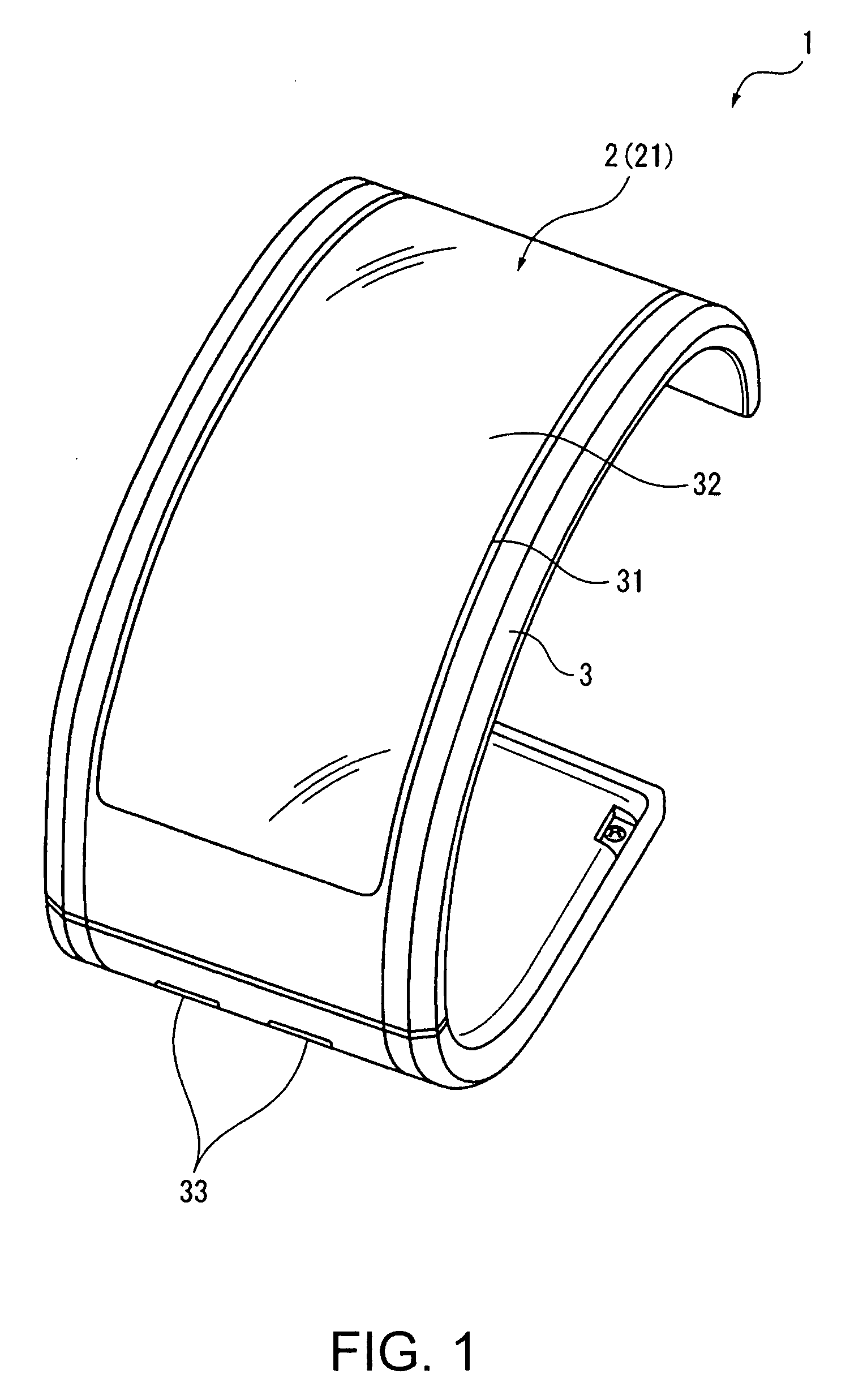
[0053]FIG. 1 is an oblique view of a timepiece 1 according to a preferred embodiment of the invention.

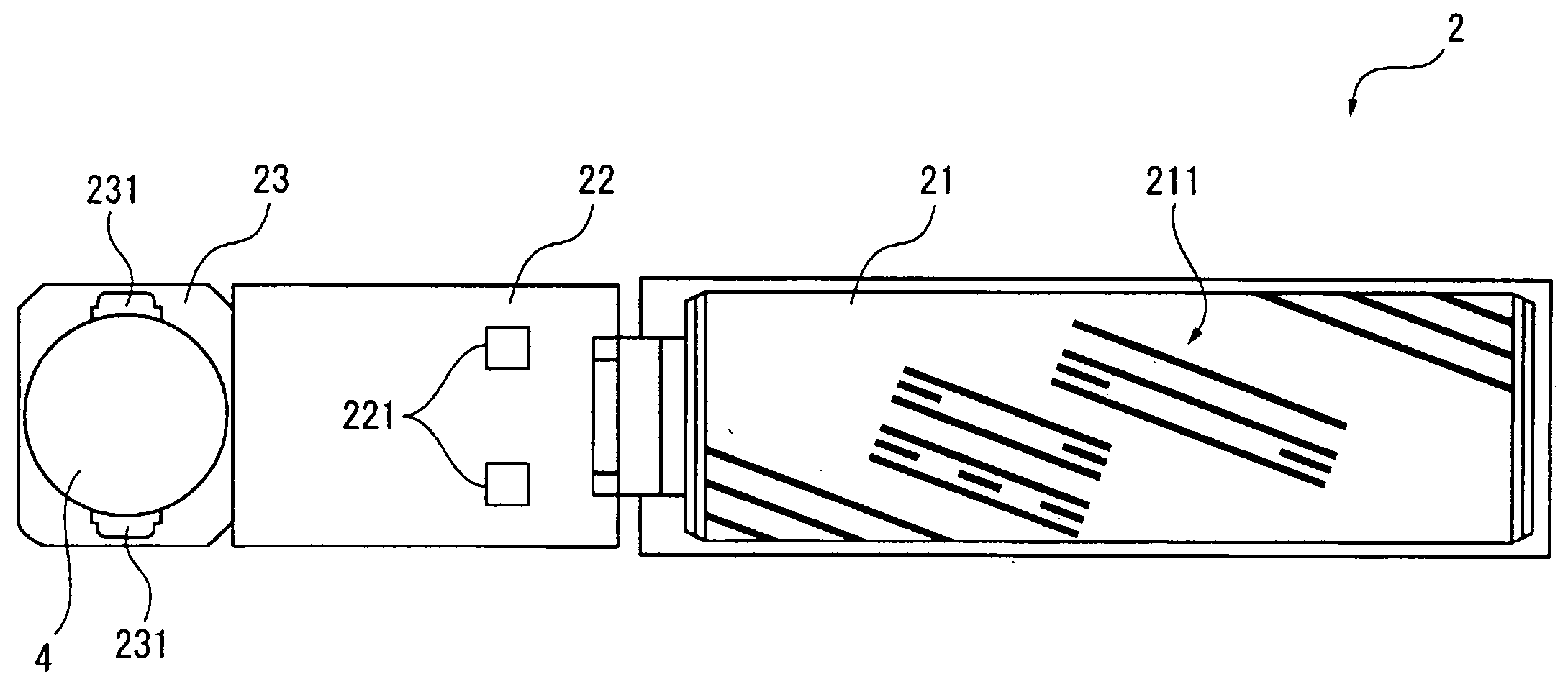
[0054]This timepiece 1 is described as a wristwatch that is worn as a bracelet on the user's wrist, for example, and as shown in FIG. 1 has a display device 2 for displaying time and date information, and a case 3 that holds the display device 2 inside.

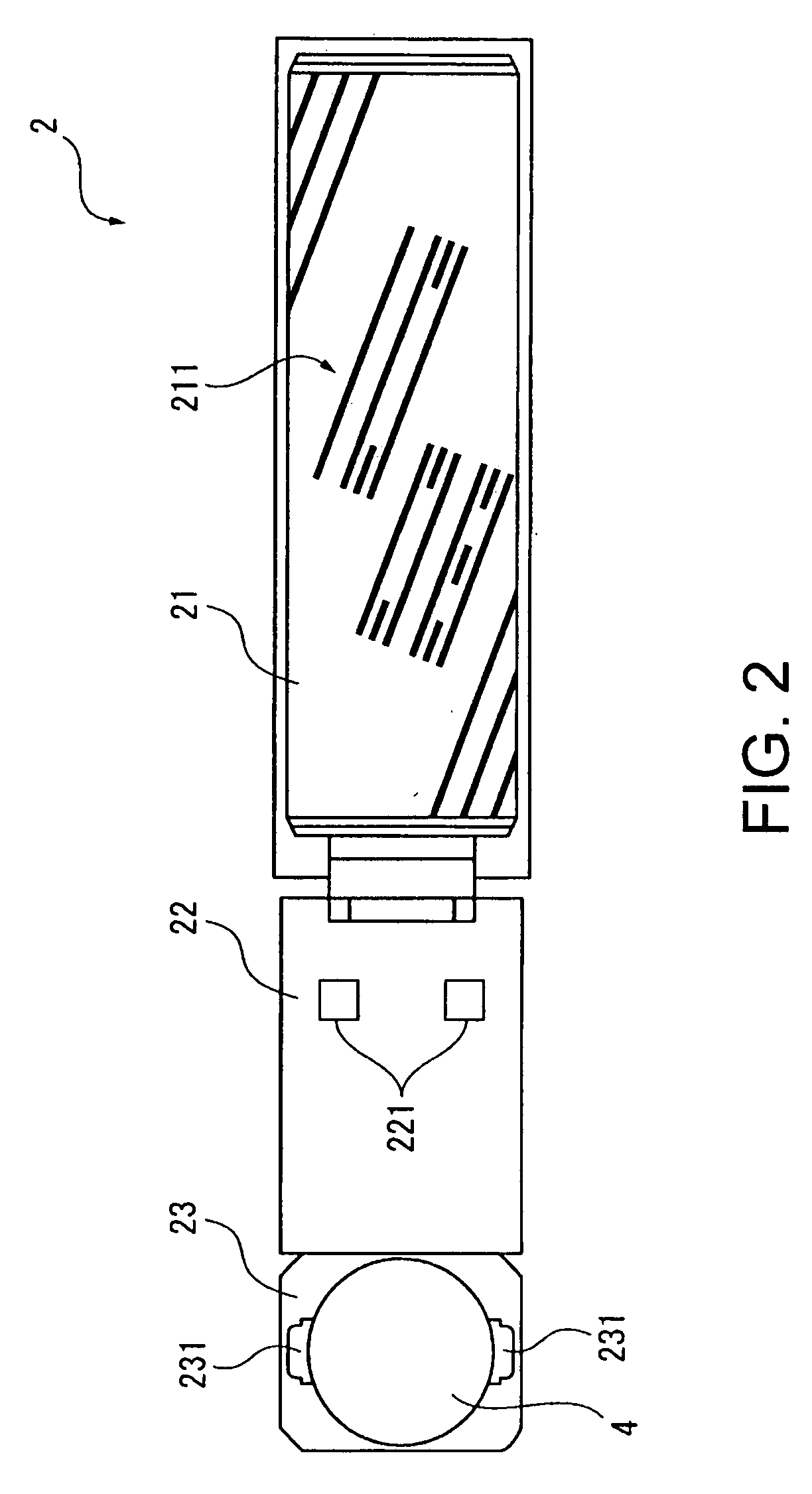
[0055]The case 3 is basically C-shaped when seen from the side to conform to the general shape of the user's wrist. A window 31 in which the display panel 21 of the display device 2 (see FIG. 2) is exposed is formed in the case 3, and a transparent cover 32 that covers the window 31 and protects the display panel 21 is disposed in the window 31. Two buttons 33 are disposed in line with each other in the case 3 so that pressing the buttons 33 depresses a corresponding pressure sensitive means...


PUM


Abstract

A display device having an electrophoretic display panel that has two types of electrophoretic elements of different color and polarity disposed between electrodes, and changes display state according to an applied voltage, and a drive means for driving the electrophoretic display panel by applying a voltage between the electrodes. The drive means has a storage means for storing color transition information correlating the color levels displayed by the electrophoretic elements to the color level that is displayed when a positive pulse is applied and the color level that is displayed when a negative pulse is applied to the electrode connected to the electrophoretic elements displaying a particular color level; a target value setting means for setting as a target value the color level to be displayed by the electrophoretic elements; and a pulse applying means for applying a pulse of a specific voltage level to the electrode at least until a current value denoting the current color level of the electrophoretic elements matches the target value. The pulse applying means has a value determination unit for determining if the current value and the target value match, a pulse application unit for applying either a positive pulse or a negative pulse to the electrode so that the current value approaches the target value if the value determination unit determines the current value and the target value do not match, a transition value acquisition unit for getting from the color transition information a transition value denoting the color level after the pulse is applied, and a current value updating unit for updating the current value to the transition value.

Description

BACKGROUND[0001]1. Technical Field[0002]The present invention relates to a display device having an electrophoretic display panel containing electrophoretic particles, and to a timepiece having the display device.[0003]2. Related Art[0004]Display devices having a display unit for displaying the time and a control means for controlling displaying content on the display unit are known from the literature. An example of such a display device is the display device (electrophoretic display panel) having electrophoretic particles as taught in Japanese Unexamined Patent Appl. Pub. JP-A-S52-70791.[0005]The electrophoretic display panel taught in JP-A-S52-70791 has an electrophoretic dispersion contained between a transparent common electrode and segment electrodes. The electrophoretic display dispersion is black and contains negatively charged color particles and positively charged white particles. When a potential difference is created between the transparent electrode and the segment elec...

Claims


Application Information

Patent Timeline
Patent Type & Authority Applications(United States)
IPC IPC(8): G09G3/34
CPCG09G3/2011G09G3/344G09G2340/16G09G2320/0242G09G2310/0254
Inventor NAGASAKI, SHINTARO
Owner E INK CORPORATION
Why Eureka
Try Eureka