Optical logic devices having polarization-based logic level representation and method of designing the same

a logic level and logic level technology, applied in logic circuits, pulse techniques, instruments, etc., can solve the problems of inefficient prior art optical gates, and complex parallel procedures

Active Publication Date: 2007-12-27
ZAGHLOUL YASSER A +1
View PDF10 Cites 5 Cited by
  • Summary
  • Abstract
  • Description
  • Claims
  • Application Information

AI Technical Summary

Benefits of technology

[0007] In another embodiment, there is provided an apparatus and method that receives an input polarized beam having a first relative amplitude and a first relative polarization angle, wherein the input polarized beam represents a first logic state or a second logic state based on the first relative polarization angle. The apparatus and method split the input polarized beam into a first beam and a second be

Problems solved by technology

Additionally, existing optical gates include costly components such as uniaxial crystals, nonlinear optical elements, and semiconductor-type photo-dete

Method used


Image

  • Optical logic devices having polarization-based logic level representation and method of designing the same
  • Optical logic devices having polarization-based logic level representation and method of designing the same
  • Optical logic devices having polarization-based logic level representation and method of designing the same

Examples


Embodiment Construction

[0036] The present inventions now will be described more fully hereinafter with reference to the accompanying drawings, in which some, but not all embodiments of the inventions are shown. Indeed, these inventions may be embodied in many different forms and should not be construed as limited to the embodiments set forth herein; rather, these embodiments are provided so that this disclosure will satisfy applicable legal requirements. Like numbers refer to like elements throughout.

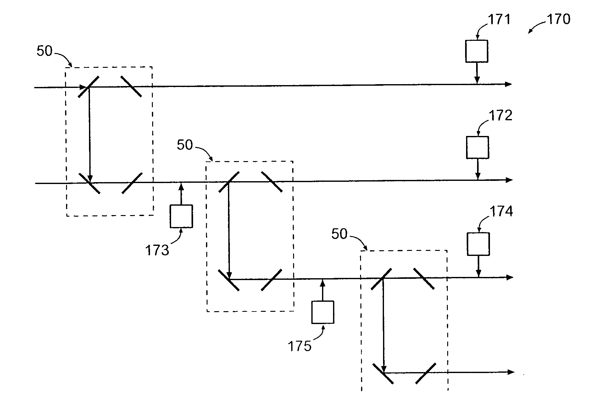
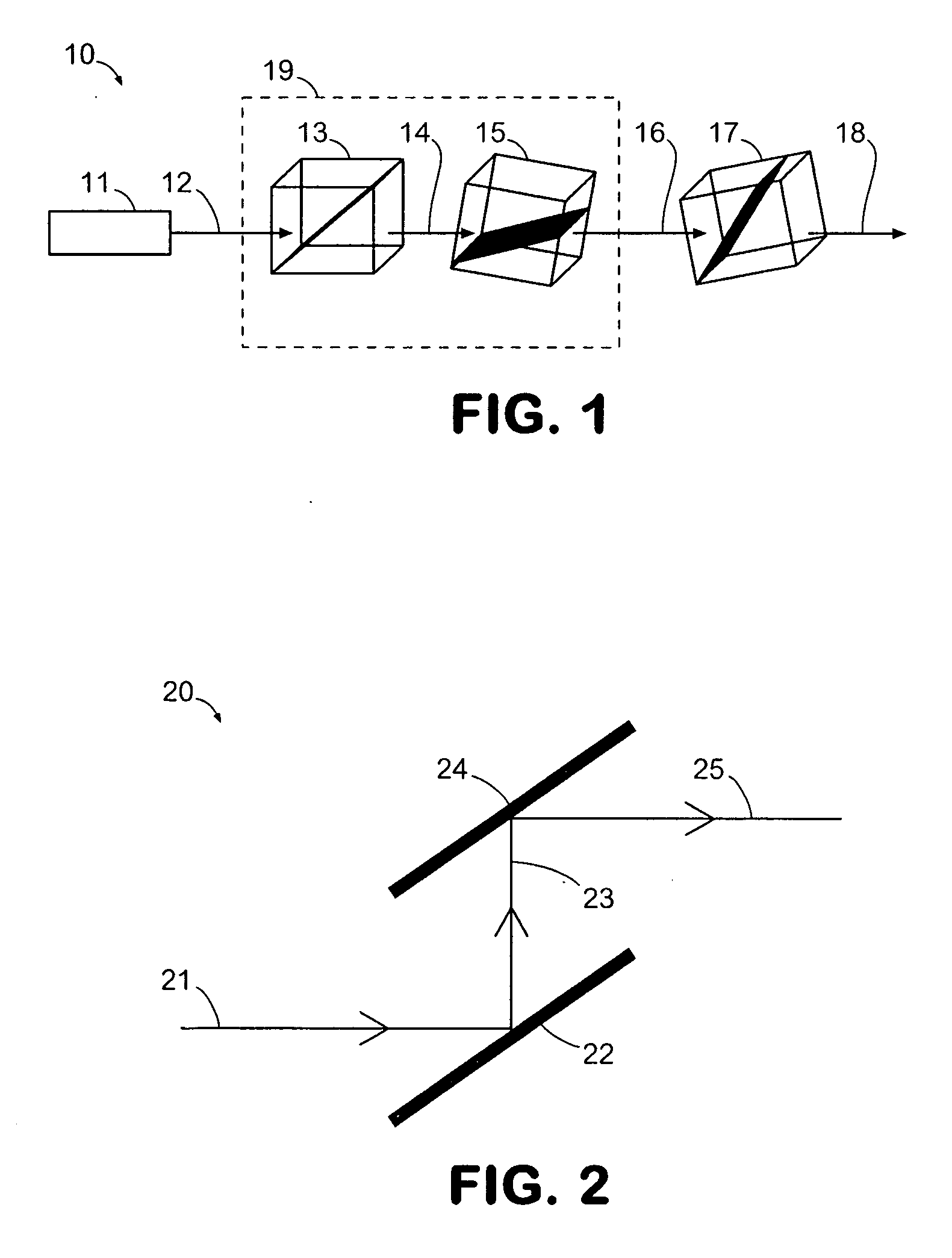
[0037]FIG. 1 illustrates a general two-electronic-signal (TES) binary gate architecture, constructed of a collection of optical devices that are cascaded together. Each device is a thin-film polarization device, or an electro-optic device, that is designed to take two positions.

[0038]FIG. 1 illustrates a general optical system 10 according to principles of the invention, which may comprise a beam generator 11 that generates a beam 12 such as an electromagnetic wave 12 and a collection of optical devices 13,...


PUM


Abstract

Apparatus and methods for implementing logical operations using polarization-based logic level representation is provided. An apparatus and method split an input polarized beam into a first beam and a second beam, wherein the first beam and the second beam have an identical or nearly identical relative polarization angle that equals or nearly equals the relative polarization angle of the input polarized beam. The apparatus and method further polarize at a first relative polarization angle the first beam and polarize at a second relative polarization angle the second beam. The ratio of the amplitudes of two perpendicular polarization components of the input polarized beam is one or nearly one and the difference between the first relative polarization angle and the second relative polarization angle is 180 degrees or nearly 180 degrees. Furthermore, the relative polarization angle of the input polarized beam equals or nearly equals either the first relative polarization angle or the second relative polarization angle.

Description

CROSS REFERENCE TO RELATED APPLICATION [0001] This application claims priority to U.S. Provisional Application No. 60 / 747,656, filed on May 18, 2006, U.S. Provisional Application No. 60 / 747,901, filed on May 22, 2006, and U.S. Provisional Application No. 60 / 827,630, filed on Sep. 29, 2006, which all are incorporated herein by reference.FIELD OF THE INVENTION [0002] Embodiments of the present invention relate generally to binary logic gates using polarization-based logic state representation. BACKGROUND OF THE INVENTION [0003] Binary logic gates implement logical operations on logic inputs to produce a logic output. The logic level (or state) of each logic input and output is either 0 (i.e., low) or 1 (i.e. high). In electrical systems, the logic level of an input or output is represented by its voltage level where typically a low voltage represents a logic 0 and a high voltage represents a logic 1. Similarly, prior art optical systems represent logic levels based on the intensity of...

Claims


Application Information

Patent Timeline
IPC IPC(8): G02F3/00
CPCG02F1/0136G02F2203/07G02F3/00
Inventor ZAGHLOUL, YASSER A.ZAGHLOUL, ABDEL RAHMAN M.
Owner ZAGHLOUL YASSER A
Why Eureka
Try Eureka