Heat sink

Inactive Publication Date: 2007-12-27
OSRAM SYLVANIA INC
View PDF6 Cites 45 Cited by
  • Summary
  • Abstract
  • Description
  • Claims
  • Application Information

AI Technical Summary

Benefits of technology

[0005]It is another object of the inventi

Problems solved by technology

As the light output demands have risen it has become necessary to increase the power to these light sources with a concomitant increase in the amount of heat generated when th

Method used


Image

  • Heat sink
  • Heat sink

Examples


Embodiment Construction

[0010]For a better understanding of the present invention, together with other and further objects, advantages and capabilities thereof, reference is made to the following disclosure and appended claims taken in conjunction with the above-described drawings.

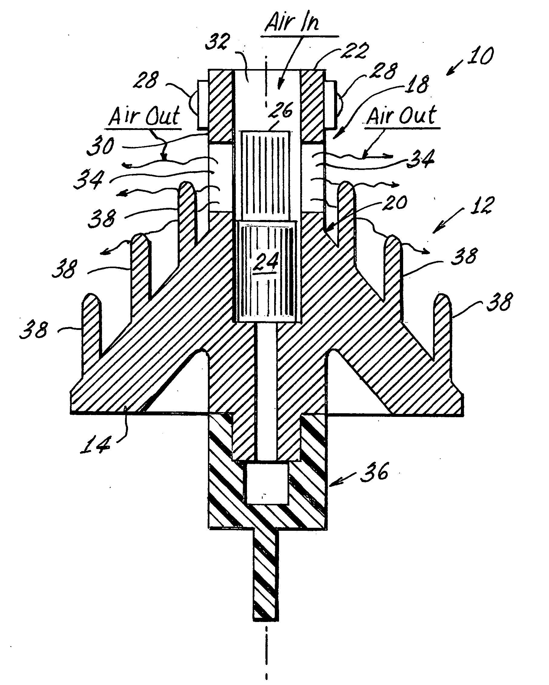
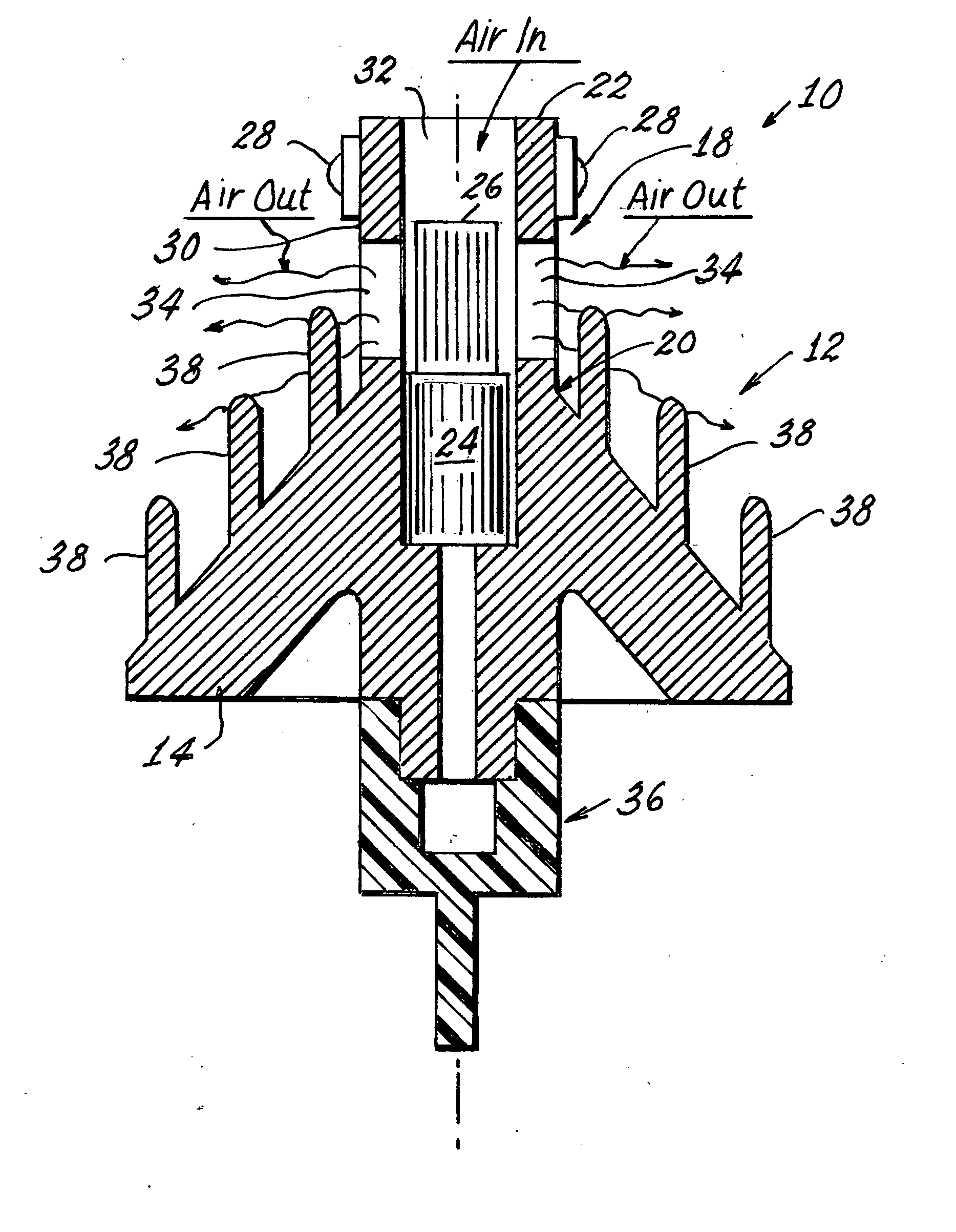
[0011]Referring now to the drawing with greater particularity, there is shown an LED lamp 10 that comprises a housing 12 having a heat conductive body 14 arrayed about a longitudinal axis 16 with a tubular projection 18 extending therefrom coaxial with the longitudinal axis 16, the tubular projection 18 having a distal end 20 attached to the heat conductive body 14 and a proximal end 22 opposite thereto. In a preferred embodiment of the invention the body 12 is formed of a cast metal or metal alloy such as copper, aluminum or zinc or a heat conductive plastic.

[0012]A motor 24 is positioned within the cavity of the tubular projection 18 and has a tubular, vaned or rotary cage type fan blade 26 operatively connected thereto. The fa...


PUM


Abstract

An LED lamp has a housing comprising a heat conductive body arrayed about a longitudinal axis with a tubular projection extending therefrom coaxial with the longitudinal axis. The tubular projection has a distal end attached to the heat conductive body and a proximal end opposite thereto. A motor is positioned within the tubular projection and has a tubular, vaned fan blade operatively connected thereto. A plurality of LED components is attached to an outside surface of the tubular projection at the proximal end. An air inlet is formed at the proximal end of the tubular projection and a plurality of air outlets are spaced about the tubular projection between the distal end of the tubular projection and the LED components. A base is operatively attached to the housing for attachment to a power supply.

Description

TECHNICAL FIELD[0001]This invention relates generally to heat sinks and more particularly to heat sinks for LED lamps. Still more particularly, it relates to an LED lamp utilizing such a heat sink as an integral part of the lamp.BACKGROUND ART[0002]Light emitting diodes (LED or LEDs) are solid-state light sources that are noted for their long life and brilliant, saturated color emission. They have found increasing use in automotive applications as center high mount stoplights and tail lights. As the light output demands have risen it has become necessary to increase the power to these light sources with a concomitant increase in the amount of heat generated when the lights are operating. Since subjecting the solid-state light sources to high heat detrimentally effects their operation, heat sinks are employed to remove the generated heat. In the past these heat sinks have generally been added-on constructions attached to the light source.[0003]It would be an advance in the art to pro...

Claims


Application Information

Patent Timeline
IPC IPC(8): F21V29/00
CPCF21K9/00F21S48/325F21V29/02F21Y2101/02F21V29/74H01L2924/0002H01L23/467F21V29/677H01L2924/00F21Y2115/10F21Y2107/30F21K9/20F21S45/43F21V29/67F21V29/60F21V29/767
Inventor COUSHAINE, CHARLES M.
Owner OSRAM SYLVANIA INC
Why Eureka
Try Eureka