
Wireless sensor power management

Pending Publication Date: 2021-12-02
CARRIER CORP
View PDF2 Cites 0 Cited by
  • Summary
  • Abstract
  • Description
  • Claims
  • Application Information

AI Technical Summary

Benefits of technology

The patent allows wireless sensors to update their parameters based on changes in certain conditions, which helps improve their performance.

Problems solved by technology

Often, the sampling interval is too short, resulting in reduced battery life.

Method used


Image

  • Wireless sensor power management
  • Wireless sensor power management
  • Wireless sensor power management

Examples


Embodiment Construction

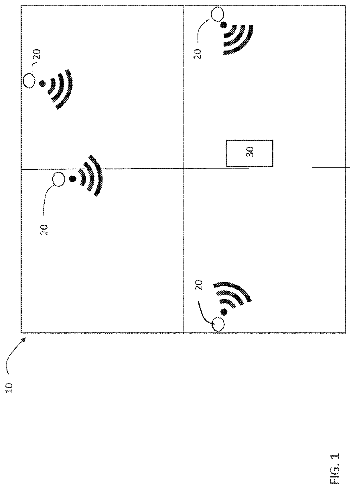
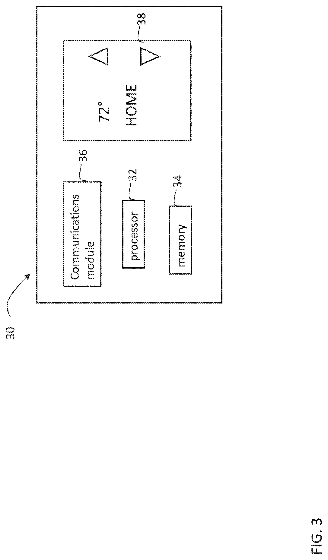
[0030]FIG. 1 depicts a building 10 equipped with wireless sensors 20 in an embodiment. The wireless sensors 20 may be part of an environmental control system (e.g., HVAC system). The wireless sensors 20 measure one or more environmental values (e.g., temperature, humidity, occupancy, etc.) and send the sensed environmental values to a controller 30. The wireless sensors 20 may be arranged in a plurality of zones within the building 10, such that each wireless sensor 20 is associated with a respective zone. A controller 30 receives the sensed environmental values from the wireless sensors 20 and controls the environmental control system. For example, the controller 30 can increase or decrease the temperature in a zone based on the sensed temperature in that zone.

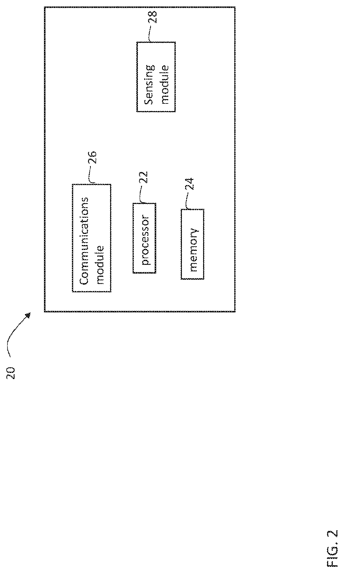
[0031]Each wireless sensor 20 may be programmed with one or more parameters. One example parameter is a sampling interval. To conserve battery life, each wireless sensor 20 has a low power mode where the sensor does not activ...


PUM


Abstract

A method for controlling an environment control system having a controller and a wireless sensor includes determining, at the controller, that a condition exists to initiate updating a parameter of the wireless sensor; determining, at the controller, an updated parameter in response to the condition; transmitting the updated parameter from the controller to the wireless sensor; storing, at the wireless sensor, the updated parameter.

Description

BACKGROUND[0001]The present disclosure relates to the management of wireless sensors, and more particularly, to the management of wireless sensor parameters to improve wireless sensor battery life.[0002]Many systems use wireless sensors to sample values. For example, in a heating, ventilation and air conditioning (HVAC) system, wireless sensors may be used to sample environmental values such as temperature or humidity. Wireless sensors often employ a low power mode or sleep state to conserve battery life. Parameters of the wireless sensor can affect battery life. For example, a sampling interval stored in the wireless sensor controls when the wireless sensor exits low power mode, makes a measurement and communicates with a controller. Often, the sampling interval is too short, resulting in reduced battery life.BRIEF DESCRIPTION[0003]In one embodiment, a method for controlling an environment control system having a controller and a wireless sensor includes determining, at the control...

Claims


Application Information

Patent Timeline
IPC IPC(8): H04W52/02H04L29/08H04W4/38
CPCH04W52/0216H04L67/125H04W84/18H04W52/0219H04W4/38H04W52/0258Y02D30/70H04L67/62
Inventor LI, JINGGERVAIS, MATHEW
Owner CARRIER CORP
Learn More