Optical connector

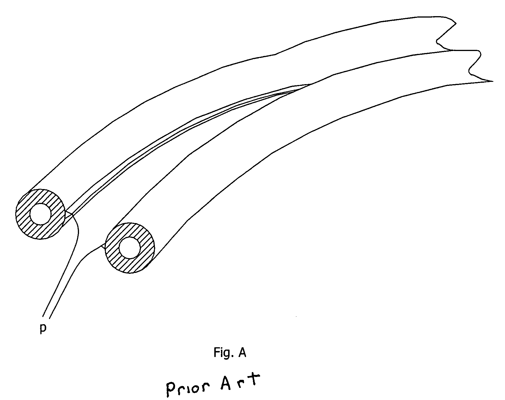
a technology of optical connectors and connectors, applied in the field of optical connectors, can solve the problems of cable eccentricity in the hole, interference with the proper alignment between the core of the optical fibre and the optical element, and damage or additional material on the circumference of the jacket of each strand,

Active Publication Date: 2007-12-27
FIRECOMMS
View PDF95 Cites 10 Cited by
  • Summary
  • Abstract
  • Description
  • Claims
  • Application Information

AI Technical Summary

Problems solved by technology

If this is done by hand, or by the use of low-cost tooling, some damage or additional material may be present on the circumference of the jacket of each strand where they have been separated.
A with the letter P. When the strand is inserted into a locating hole this additional material may cause the cable to be eccentric in the hole.
This may interfere with the proper alignment between the core of the optical fibre and the optical element.

Method used


Image

  • Optical connector
  • Optical connector
  • Optical connector

Examples


Embodiment Construction

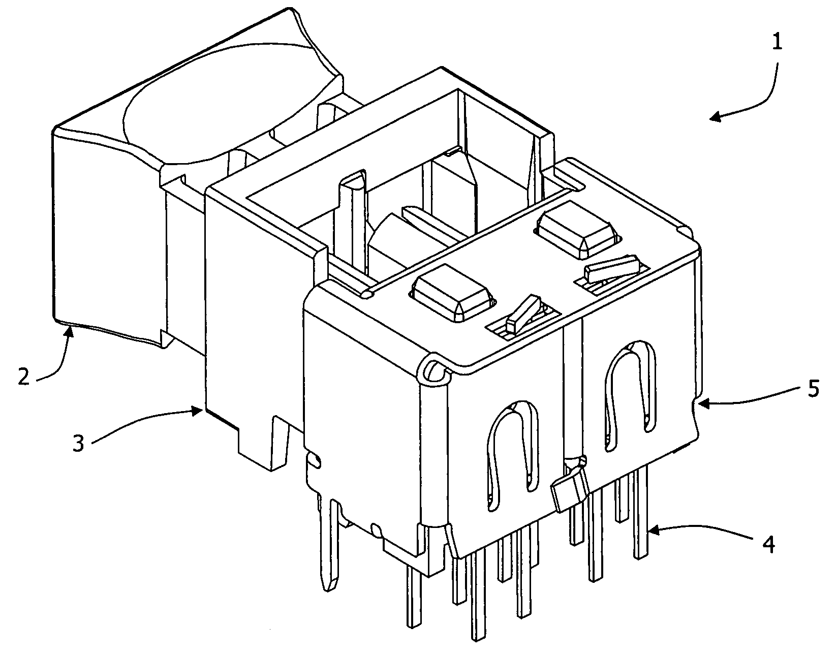
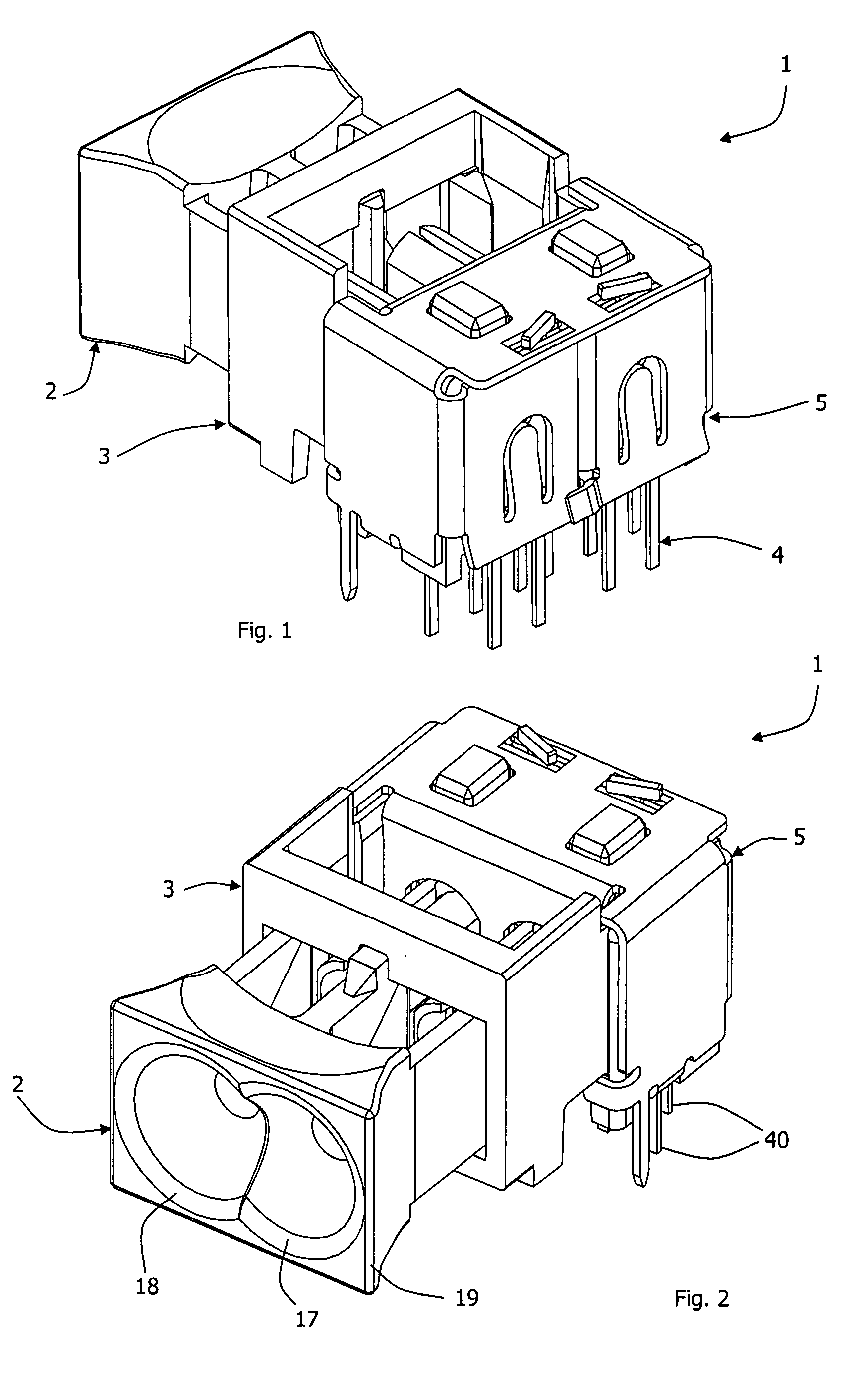
[0054]Referring to FIGS. 1 to 10 an optical connector 1 comprises four main components, namely:

[0055]2, a clamp;

[0056]3, a housing into which the clamp 2 slides;

[0057]4, two optical elements, a transmitter and a receiver; and

[0058]5, an EMI metal shield surrounding the elements 4.

[0059]The clamp 2 has two parallel through holes 10 and 11 for receiving fibre terminations, each through-hole having a generally conical mouth 17, 18 for convenient guidance of a fibre termination. Inside of the through-holes 10 and 11 there are side resilient clamp members 12, and there is a single central clamp member 13. The clamp 2 is of moulded plastics construction, and the clamp members 12 are resilient in the lateral plane. The central clamp member 13 on the other hand has little flexibility and remains essentially static throughout the clamping operation. Each resilient clamping member 12 has a tooth 15 at its end for snap-fitting engagement with the housing 3 at open and closed positions, as desc...


PUM


Abstract

An optical connector comprises four main components, namely a clamp; a housing into which the clamp slides; two optical elements, a transmitter and a receiver; and an EMI metal shield surrounding the elements. The clamp has two parallel through holes for receiving fibre terminations, each through-hole having a generally conical mouth for convenient guidance of a fibre termination. Inside of the through-holes there are side resilient clamp members, and there is a single central clamp member. The clamp is of moulded plastics construction, and the clamp members are resilient in the lateral plane. The central clamp member on the other hand has little flexibility and remains essentially static throughout the clamping operation. Each resilient clamping member has a tooth at its end for snap-fitting engagement with the housing at open and closed positions. Fibre terminations are inserted through the clamp mouths and the through-holes and into the sockets of the housing. The clamp is then simply pushed inwardly so that teeth in the socket walls bite into the fibre claddings.

Description

INTRODUCTION[0001]1. Field of the Invention[0002]The invention relates to coupling of optic fibres with optical elements or other fibres.[0003]2. Prior Art Discussion[0004]Optical fibres are commonly used for transmitting light from one location to another, either to communicate data (by switching on and off the light, or by varying its intensity) or to provide illumination. At one or both ends of the optical fibre it is necessary to couple the fibre to an optical element. This element may be a light transmitting element, from which light will enter the fibre; a light detecting element, to detect light transmitted through the fibre; a light guide of some other type, for example a lens to guide light to or from the end of the fibre; or the end of another fibre, in cases where a number of fibres are coupled together to accomplish a purpose.[0005]Optical Fibres may be made of glass (silica), or of plastics (such as PMMA or Polycarbonate) or of a composite construction, such as a silica...

Claims


Application Information

Patent Timeline
IPC IPC(8): G02B6/00
CPCG02B6/3801G02B6/3855G02B6/4292G02B6/4277G02B6/4201G02B6/4256
Inventor MORIARTY, THOMASDOYLE, PATRICK
Owner FIRECOMMS
Why Eureka
Try Eureka