Image forming apparatus and method for distinguishing suitable parts in the same

Inactive Publication Date: 2007-12-27
OKI DATA CORP
View PDF3 Cites 31 Cited by
  • Summary
  • Abstract
  • Description
  • Claims
  • Application Information

AI Technical Summary

Benefits of technology

[0007]It is an objective of the present invention, in consideration of the technical problems described above, to provide an image forming apparatus that enables a maintenance personnel of the manufacturer or the like to be aware of the usage condition even where the unsuitable toner cartridge is continuously used and that restricts the use of the unsuitable toner cartridge by informing a user of the usage condition as described above, and to further provide a method for distinguishing the suitable parts in the aforementioned image forming apparatus.

Problems solved by technology

Therefore, in a case where maintenance personnel or the like comes to perform maintenance of the image forming apparatus, the maintenance personal is aware of the information concerning the usage from the secondary storage area and can therefore restrict the use of the unsuitable replaceable part.

Method used


Image

  • Image forming apparatus and method for distinguishing suitable parts in the same
  • Image forming apparatus and method for distinguishing suitable parts in the same
  • Image forming apparatus and method for distinguishing suitable parts in the same

Examples


first embodiment

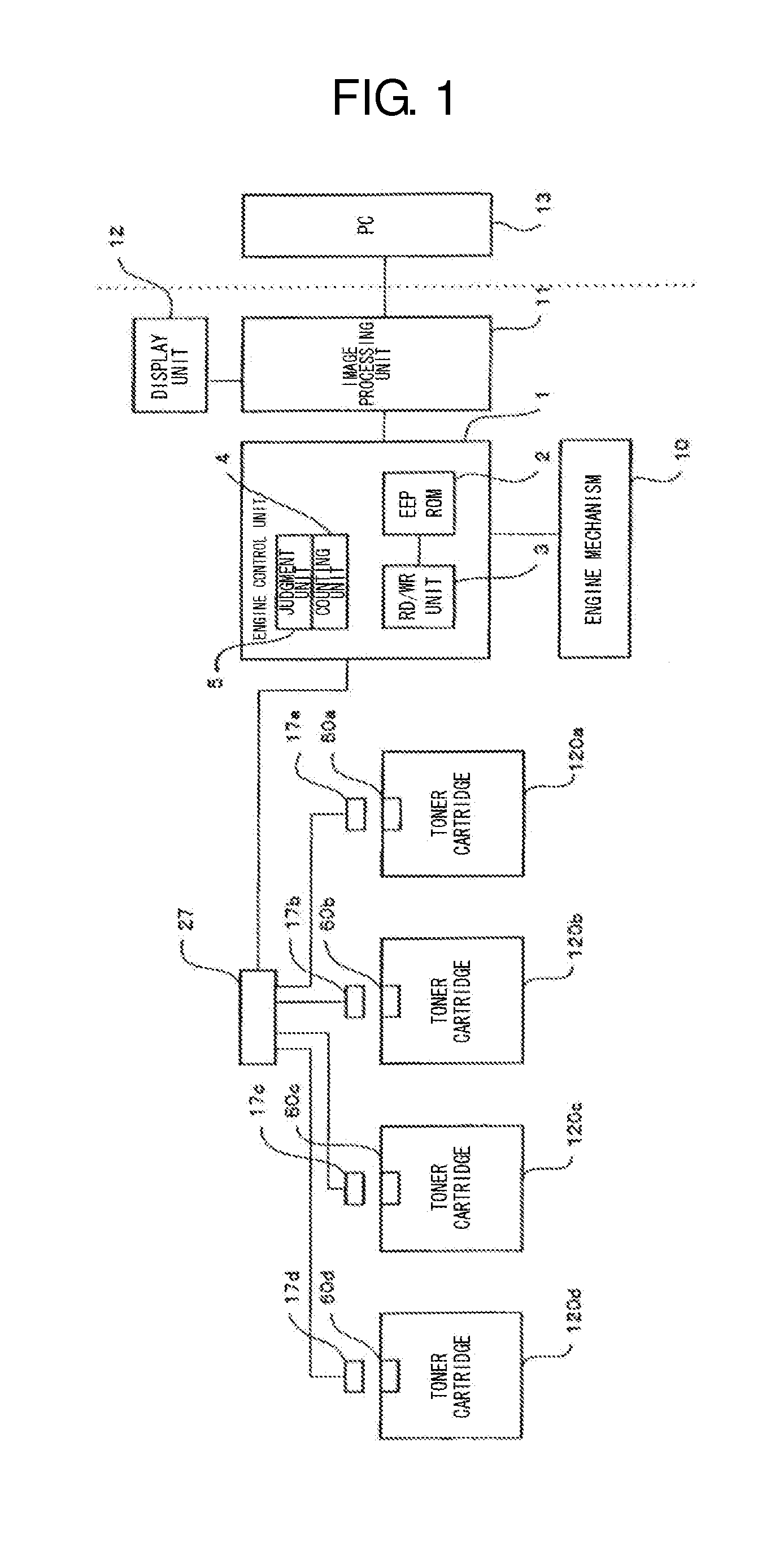
[0036]FIG. 1 is an overall block diagram of a first embodiment of the image forming apparatus according to the present invention, and is a diagram of a case where the image forming apparatus according to the embodiment is an electrophotographic color printing apparatus. In the image forming apparatus of the present embodiment, four toner cartridges 120a, 120b, 120c, 120d are disposed corresponding to four colors and each toner cartridge 120a, 120b, 120c, 120d houses a wireless tag (RFID). A wireless tag 60a is housed in an upper surface of the toner cartridge 120a and is composed of a tag chip housing nonvolatile memory and a substrate mounted with the tag chip, having an antenna pattern. Specific information concerning the toner cartridge or the like is stored in the nonvolatile memory, which serves as a primary memory section. The specific information is an ID code (8 byte) assigned at a time when the wireless tag (RFID) is created. A communication antenna 17a is affixed at a loca...

second embodiment

[0050]FIG. 11 is an overall block diagram of the color printing apparatus of the first embodiment. The difference between the apparatus of FIG. 11 and the color printing apparatus of the first embodiment shown in FIG. 1 is that a display switching unit 6 is added to the engine control unit 1. The display switching unit 6 has a function to read the value of the suitability flag and the unsuitability count value and switch the content in the display unit 12 via the image processing unit 11 based on the size of the value.

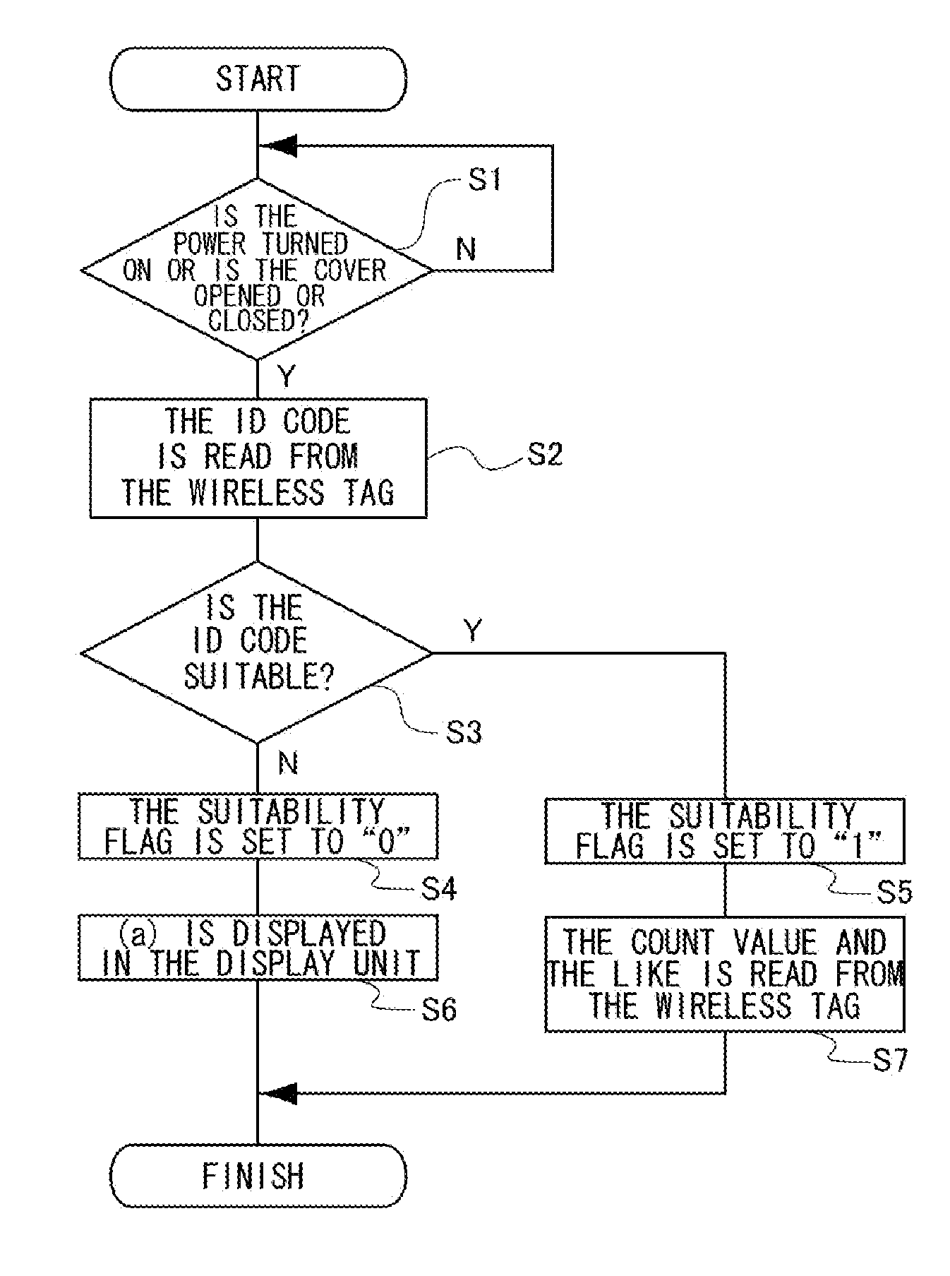
[0051]FIG. 12 is an example display at a time when the display is switched. (a) is a time at which the suitability flag is detected to be “0” but the unsuitable toner has barely (yet) to be used. For example, on the condition that the unsuitable count value is put in terms of the number of toner cartridges, where the number of toner cartridges is set to A=0.1, B=0.5, and C=2, the number less than A is displayed as (a). Next, in a case where the number of toner cartridg...

third embodiment

[0054]FIG. 14 is an overall block diagram of the image forming apparatus of the third embodiment. The difference between the apparatus of FIG. 14 and the color printing apparatus of the first embodiment shown in FIG. 1 is that a timer unit 7 is added to the engine control unit 1. The timing function of the timer unit 7 holds date and time information. The engine control unit 1 inputs the date and time information and writes the date and time information onto the EEPROM at the time when the count value by the counting unit 4 is written onto the EEPROM. FIG. 15 shows one example of data stored in the EEPROM containing the date and time information. In the suitable area and unsuitable area a separate area is preserved for the date and time information for each color, and this area is separate from the suitable area and unsuitable area for the count values. There are two kinds of information as the date and time information, the first is the initial date and time and the second is the u...


PUM


Abstract

An image forming apparatus that can provide notification, so that maintenance personnel of a manufacturer or the like can be made aware of a usage condition in a case where an unsuitable toner cartridge is intermittently used. The image forming apparatus is equipped with a primary storage section storing specific information concerning a replaceable part, such as a toner cartridge that can be attached or removed from a main body, and a secondary storage section storing information concerning usage of the replaceable part. The specific information is read from the primary storage section in a condition where the replaceable part is attached, and a judgment is made by a judgment section concerning whether the replaceable part is suitable. If the replaceable part cannot be judged as suitable, information concerning the use of the replaceable part is stored in the secondary storage section and notification is provided by a notification section.

Description

BACKGROUND OF THE INVENTION [0001]1. Field of the Invention[0002]The present invention relates to an image forming apparatus containing attachable and removable replaceable parts such as a toner cartridge or the like.[0003]2. Description of Related Art[0004]Conventionally, it is common for an electrophotographic image forming apparatus such as a copy machine, fax machine, or printer, to contain multiple development devices that each accommodate developers including prescribed toners and are disposed facing image holding bodies to make visible latent images formed on the image holding bodies. A toner supply vessel, such as a toner cartridge or toner bottle, is equipped externally to a toner supply unit of the development device at a time of maintenance for supplying the toner, for example.[0005]In such a conventional image forming apparatus, to extract a counterfeit toner cartridge, two-way communication is executed between a communication unit on the side of the toner cartridge and ...

Claims


Application Information

Patent Timeline
IPC IPC(8): G03G15/00
CPCG03G15/553G03G21/1889G03G21/1892G03G15/0863G03G2221/1823G03G15/556G03G2215/0697
Inventor KASAI, TADASHI
Owner OKI DATA CORP
Why Eureka
Try Eureka