Wireless LAN system, access point, and method for preventing connection to a rogue access point

Active Publication Date: 2008-01-03
OKI ELECTRIC IND CO LTD
View PDF4 Cites 23 Cited by
  • Summary
  • Abstract
  • Description
  • Claims
  • Application Information

AI Technical Summary

Benefits of technology

[0009]An object of the present invention is to provide a simple

Problems solved by technology

However, wireless signals pass through the walls of corporate buildings in which wireless LANs are located, so if a rogue access point 4 is set up outside a building 5 by a third party as in FIG. 2 with the intention of eavesdropping, it is difficult for a wireless LAN terminal 1-n to tell whether this access point is legitimate or not.
As wireless LAN systems are not connected by cables, however, it is difficult for a wireless

Method used


Image

  • Wireless LAN system, access point, and method for preventing connection to a rogue access point
  • Wireless LAN system, access point, and method for preventing connection to a rogue access point
  • Wireless LAN system, access point, and method for preventing connection to a rogue access point

Examples


Embodiment Construction

[0040]An embodiment of the invention will now be described with reference to the attached drawings, in which like elements are indicated by like reference characters.

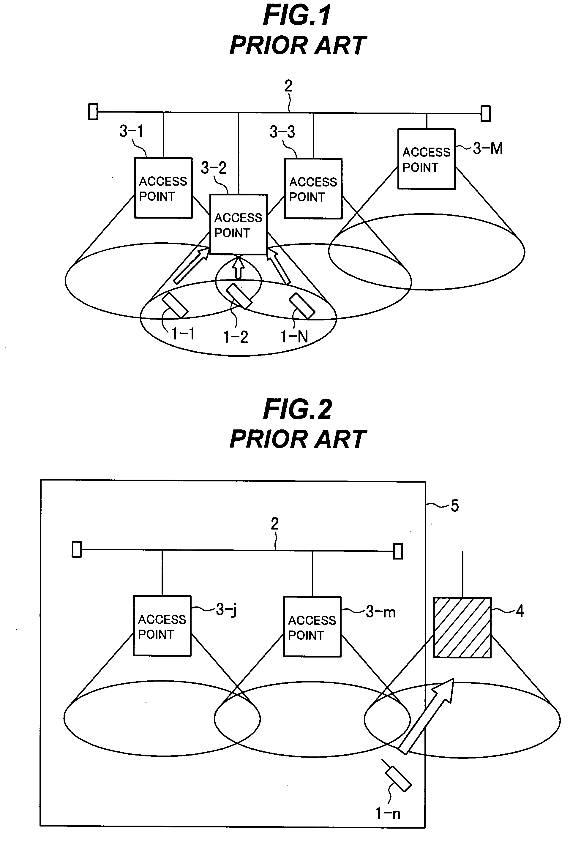
[0041]The embodiment encompasses a wireless LAN system of the type shown in FIGS. 1 and 2, at least some of its legitimate access points, and the method used by these access points to preventing connection to a rogue access point.

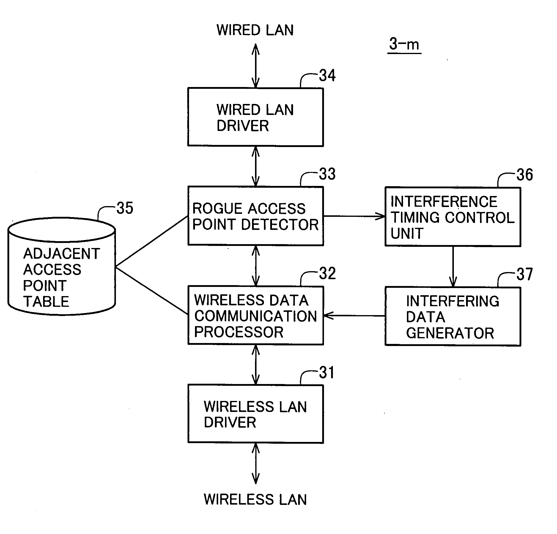
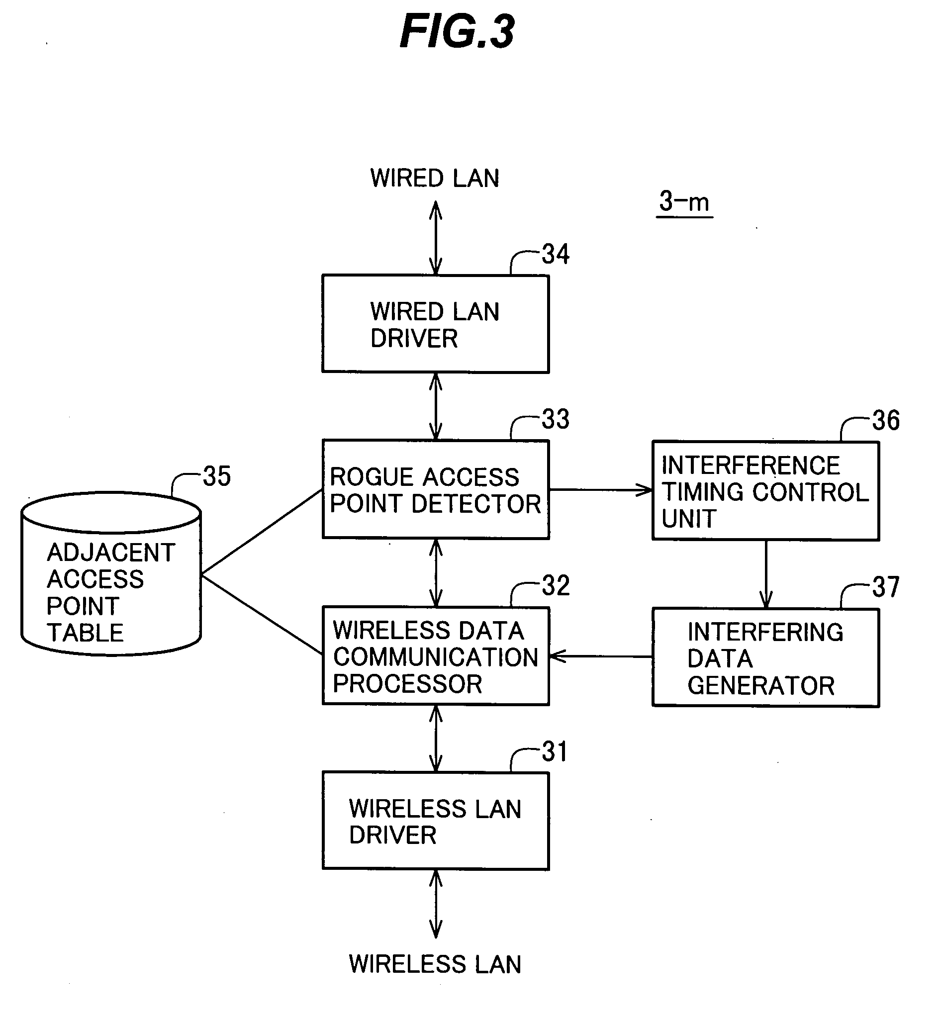
[0042]An access point in the wireless LAN system has a wireless communication unit for communicating with wireless LAN terminals in its own coverage area, a wired communication unit for communicating with the wired LAN (the wired backbone of the local area network), and a signal processing unit that passes signals between the wireless communication unit and wired communication unit and executes connection control processes.

[0043]The wireless communication unit, wired communication unit, and signal processing unit are hardware units, but the signal processing unit operates primarily by executing...


PUM


Abstract

A wireless local area network system includes one or more access points connected to a wired network which is part of the system. To prevent wireless terminals from communicating with a rogue access point that is not connected to the wired network, a legitimate access point detects the rogue access point, determines its beacon signal period, and sets a timer to generate timings at which the rogue access point is expected to transmit the beacon signals. At each of these timings, the legitimate access point creates and transmits interfering data that interfere with the rogue access point's beacon signals.

Description

BACKGROUND OF THE INVENTION[0001]1. Field of the Invention[0002]The present invention relates to a wireless local area network (LAN), more particularly to a method, access point, and system for detecting rogue access points and preventing wireless terminals from connecting with them.[0003]2. Description of the Related Art[0004]A typical corporate wireless LAN system has the structure shown in FIG. 1, in which wireless LAN terminals 1-1 to 1-N access a wired LAN 2 through access points 3-1 to 3-M, where M and N are positive integers. Japanese Patent Application Publication No. 2000-312162, for example, describes wireless LAN systems of this type.[0005]The wireless LAN terminals 1-n (where n is from 1 to N) and the access points 3-m (where m is from 1 to M) are wirelessly connected without the need of transmission cables, so the terminals have greater mobility than in a wired network. Wireless LAN systems are therefore becoming a popular type of corporate network infrastructure.[0006]...

Claims


Application Information

Patent Timeline
IPC IPC(8): H04Q7/24H04W12/122H04W84/12H04W88/08H04W92/02
CPCH04K3/22H04K3/28H04K3/41H04K3/45H04K3/65H04W92/02H04K2203/18H04W12/12H04W84/12H04W88/08H04K3/86H04W12/122
Inventor NAKANO, YOSHIHISA
Owner OKI ELECTRIC IND CO LTD
Why Eureka
Try Eureka