Stent Having Time-Release Indicator

a technology of stent and indicator, which is applied in the field of ureteral stent having an agent, can solve the problems of patient forgetting the stent, loss of fluid passage through the stent, and possible loss of kidney function

Active Publication Date: 2008-01-03
BOSTON SCI SCIMED INC
View PDF65 Cites 53 Cited by
  • Summary
  • Abstract
  • Description
  • Claims
  • Application Information

AI Technical Summary

Problems solved by technology

A problem associated with the use of such known ureteral stents is that a patient may forget the stent is disposed within the patient's body, and / or the patient may delay returning to a physician to have a stent removed after the appropriate period of time.
When this situation occurs, the stent may become encrusted or otherwise blocked, causing a loss of fluid passage through the stent and possible loss of kidney function.

Method used


Image

  • Stent Having Time-Release Indicator
  • Stent Having Time-Release Indicator
  • Stent Having Time-Release Indicator

Examples


Embodiment Construction

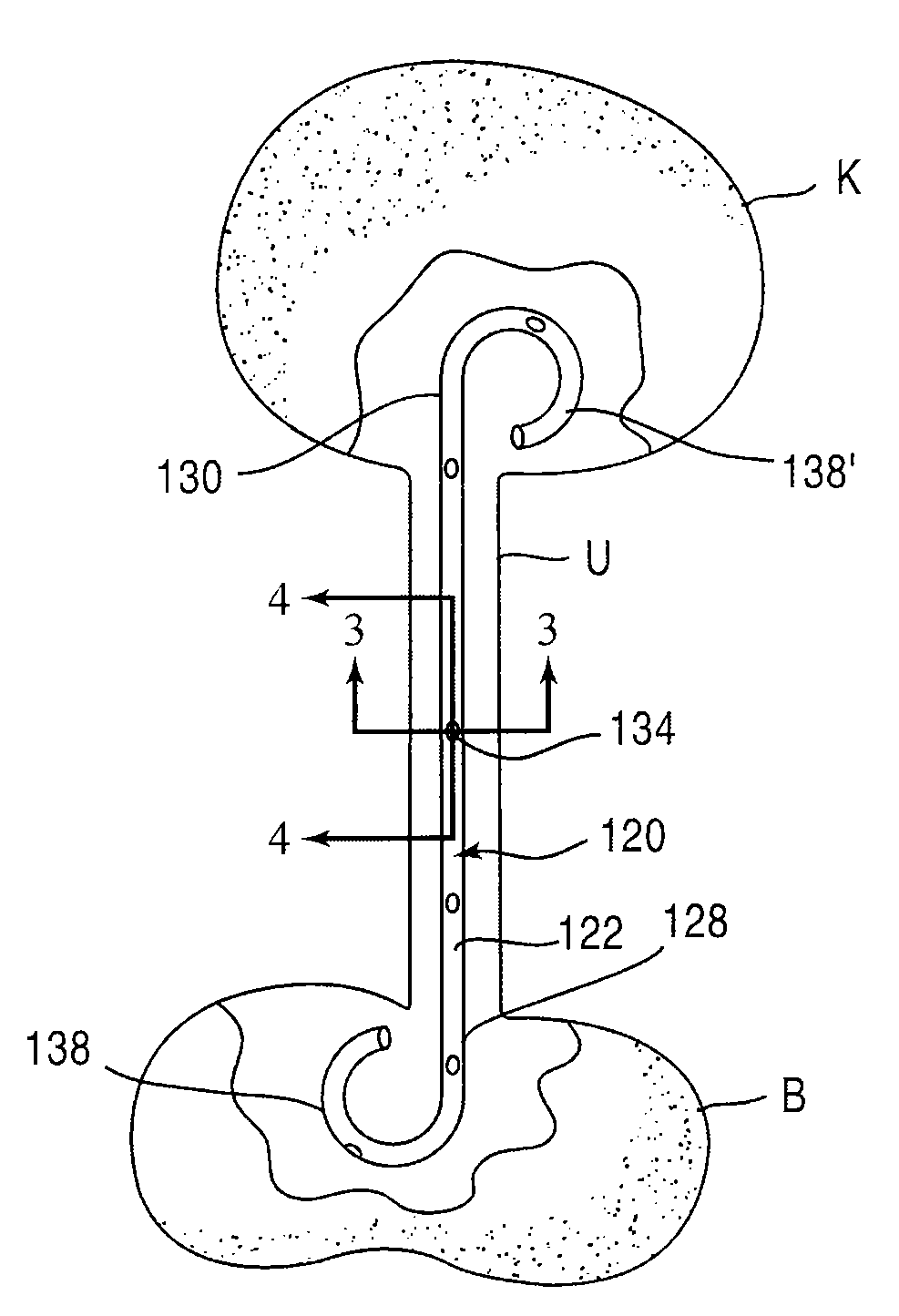
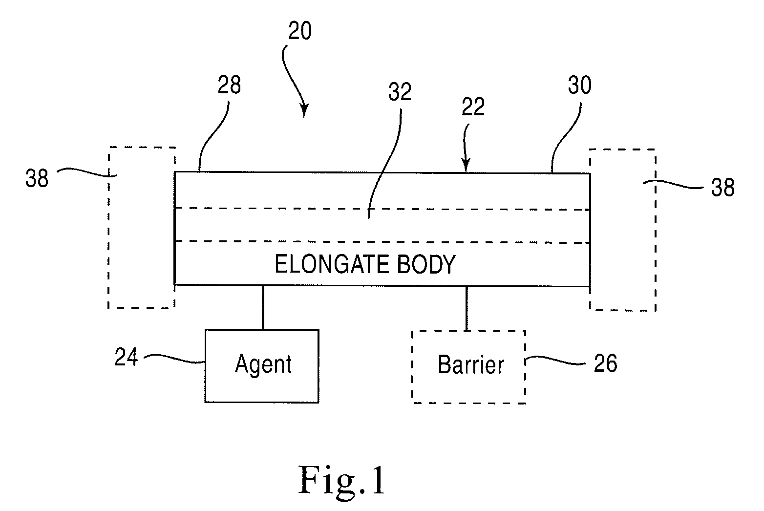
[0025]FIG. 1 is a schematic illustration of a stent according to an embodiment of the invention. A stent 20 is configured to be placed or otherwise implanted (transuretherally or percutaneously) into a urinary tract of a mammalian body.

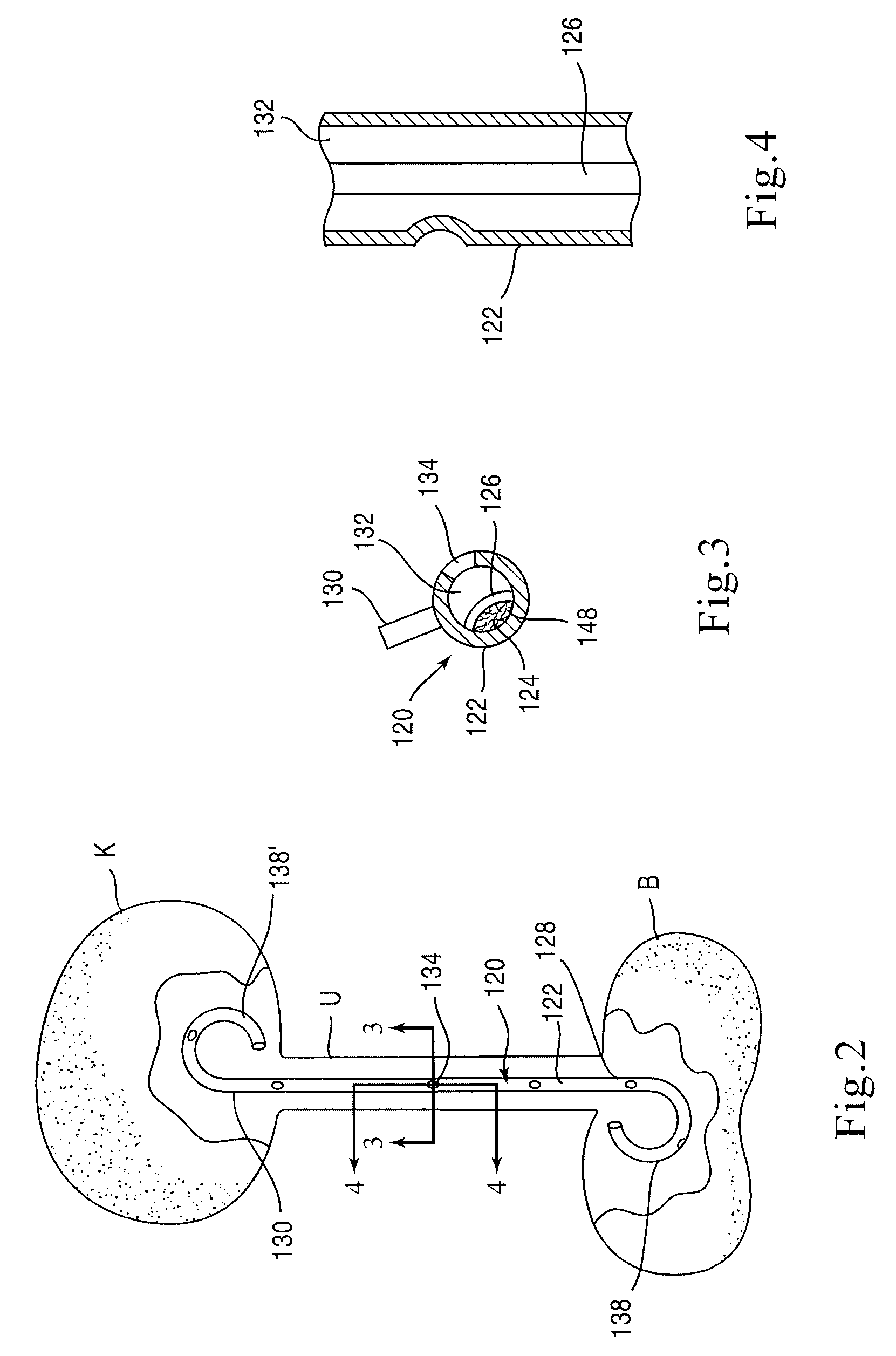
[0026]The stent 20 can include any of the conventional structures of a ureteral stent. In the embodiment illustrated schematically in FIG. 1, stent 20 includes an elongate body 22 defining a lumen 32 extending from a proximal end portion 28 to a distal end portion 30, through which urine may be conveyed. The elongate body 22 and lumen 32 can be configured in any of the conventional configurations for a ureteral stent. Similarly, each of the proximal end portion 28 and distal end portion 30 can be configured, or can include a retention member 38, to provide retention of the stent 20 within the urinary tract. The stent 20 can be disposed within the urinary tract of the patient such that the proximal end portion 28 is disposed within either a ureter or a...


PUM

PropertyMeasurementUnit
pHaaaaaaaaaa
coloraaaaaaaaaa
pHaaaaaaaaaa

Abstract

A medical device includes an elongate body configured to be disposed within a urinary tract of a patient such that a first end portion of the elongate body is disposed at a first location of the urinary tract and a second end portion of the elongate body is disposed at a second, different location of the urinary tract. The elongate body defines a lumen that is configured to convey urine from the first location of the urinary tract to the second location of the urinary tract. An agent is formulated to visually alter urine of the patient, the agent is coupled to the elongate body and releasable into the patient's urine.

Description

BACKGROUND[0001]The disclosed invention relates generally to a medical device and more particularly to a ureteral stent having an agent configured to visually alter the urine of a patient.[0002]Known ureteral stents are typically placed within a urinary tract of a patient such that one end portion of the ureteral stent is located in either a kidney or a ureter of the patient and another end portion of the ureteral stent is located in a bladder of the patient. Some known ureteral stents include retention members configured to help retain the ureteral stent in position within the patient. Known ureteral stents are typically positioned within the urinary tract of the patient by placing a guidewire within the patient, sliding the ureteral stent on the guidewire, and then forcing the ureteral stent along the guidewire into a desired position within the patient using a push cannula. After an appropriate period of time, the ureteral stent is removed from the patient, such as by pulling the...

Claims


Application Information

Patent Timeline
Patent Type & Authority Applications(United States)
IPC IPC(8): A61M1/00
CPCA61L31/148A61M27/008A61L2300/40A61L31/16A61F2250/0079A61F2250/0029A61F2250/0031A61F2250/0035A61F2210/0004A61F2250/0068A61F2250/008A61L15/56A61F2013/422A61F13/42A61F2002/9528A61F13/34A61F2002/048A61F2/04A61L31/14G01N33/84
Inventor HIXON, JESSICAKOSTELAC, BRYAN
Owner BOSTON SCI SCIMED INC
Why Eureka
Try Eureka