
External datum system and film hole positioning using core locating holes

a technology of core locating and datum, which is applied in the direction of forging/pressing/hammering equipment, lighting and heating equipment, and forging/pressing/hammering equipment, etc., can solve the problems of inconvenient use of film hole positioning, and inability to provide a film boundary layer

Inactive Publication Date: 2008-01-10
UNITED TECH CORP
View PDF13 Cites 15 Cited by
  • Summary
  • Abstract
  • Description
  • Claims
  • Application Information

AI Technical Summary

Benefits of technology

The patent describes a turbine engine structure that includes a wall with a hole in it for a locating pin. This hole is used to accurately position the structure for further processing. The structure also has other holes called film holes that intersect with the locating holes. These film holes are machined in the exterior surface of the structure and are used to transfer heat. The technical effect of this invention is that it allows for precise positioning of internal passages and other heat transfer features in the turbine engine structure.

Problems solved by technology

A time consuming trial and error process is used to correlate the desirable film holes to internal features of the hollow structure.
Furthermore, the lack of accuracy in locating the film holes often precludes the use of film holes in some desired location.
The locating holes are arranged outside of the rows and are configured such that they are not useful for providing a film boundary layer.
The locating holes are generally considered an undesired byproduct of the casting process.

Method used


Image

  • External datum system and film hole positioning using core locating holes
  • External datum system and film hole positioning using core locating holes
  • External datum system and film hole positioning using core locating holes

Examples


Embodiment Construction

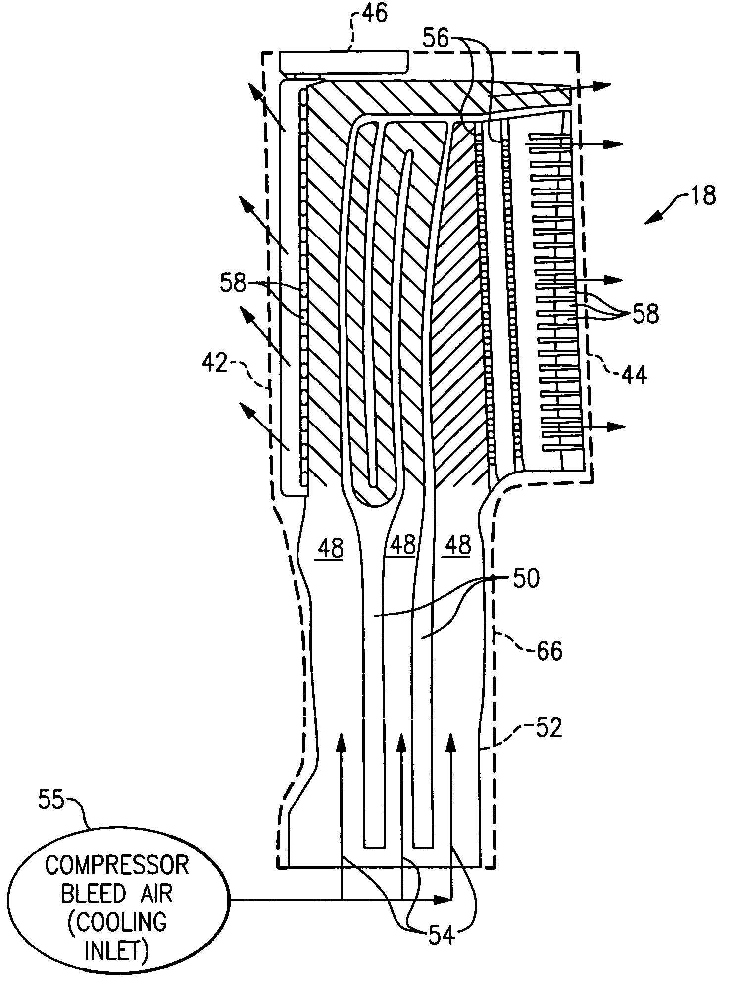
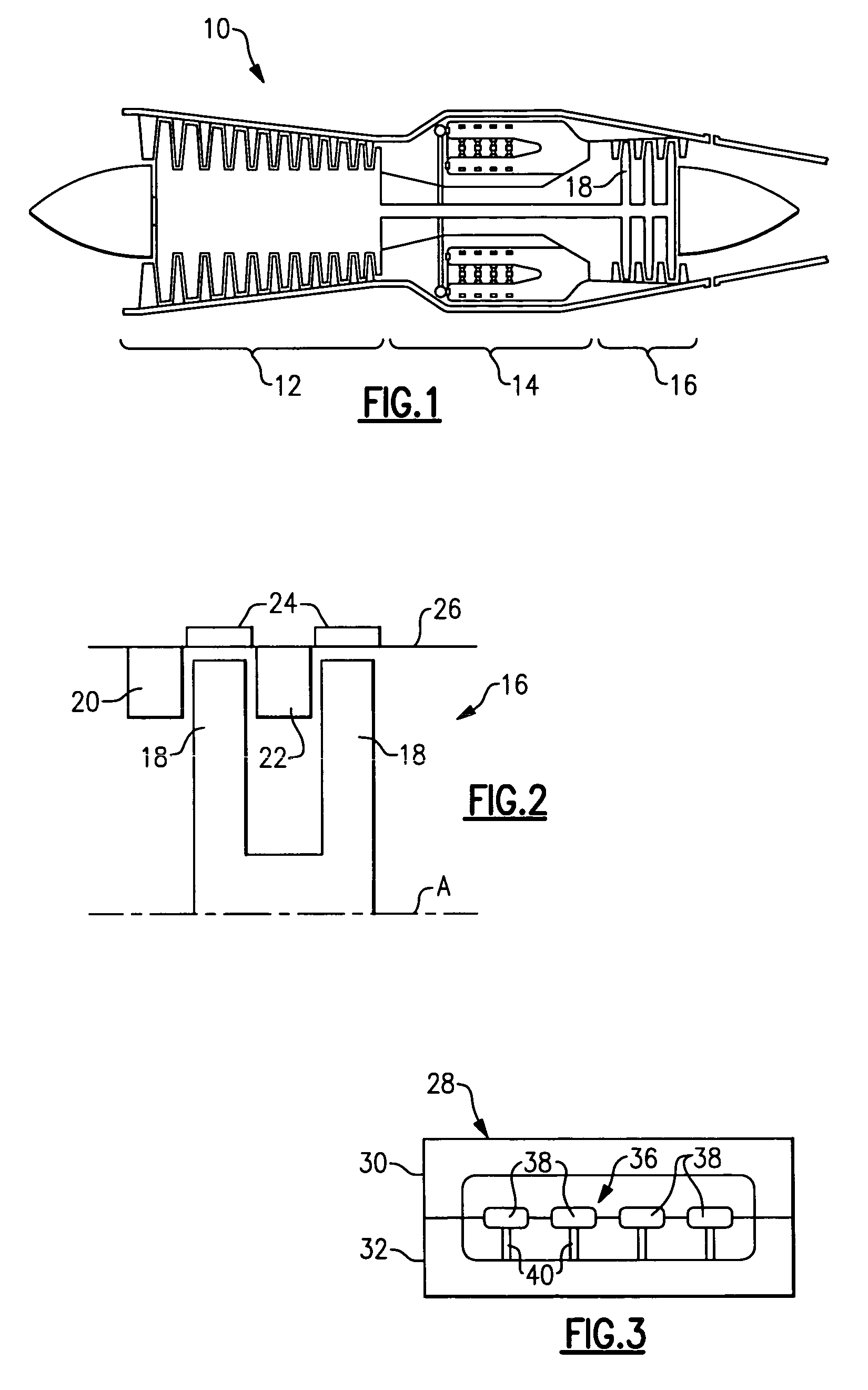
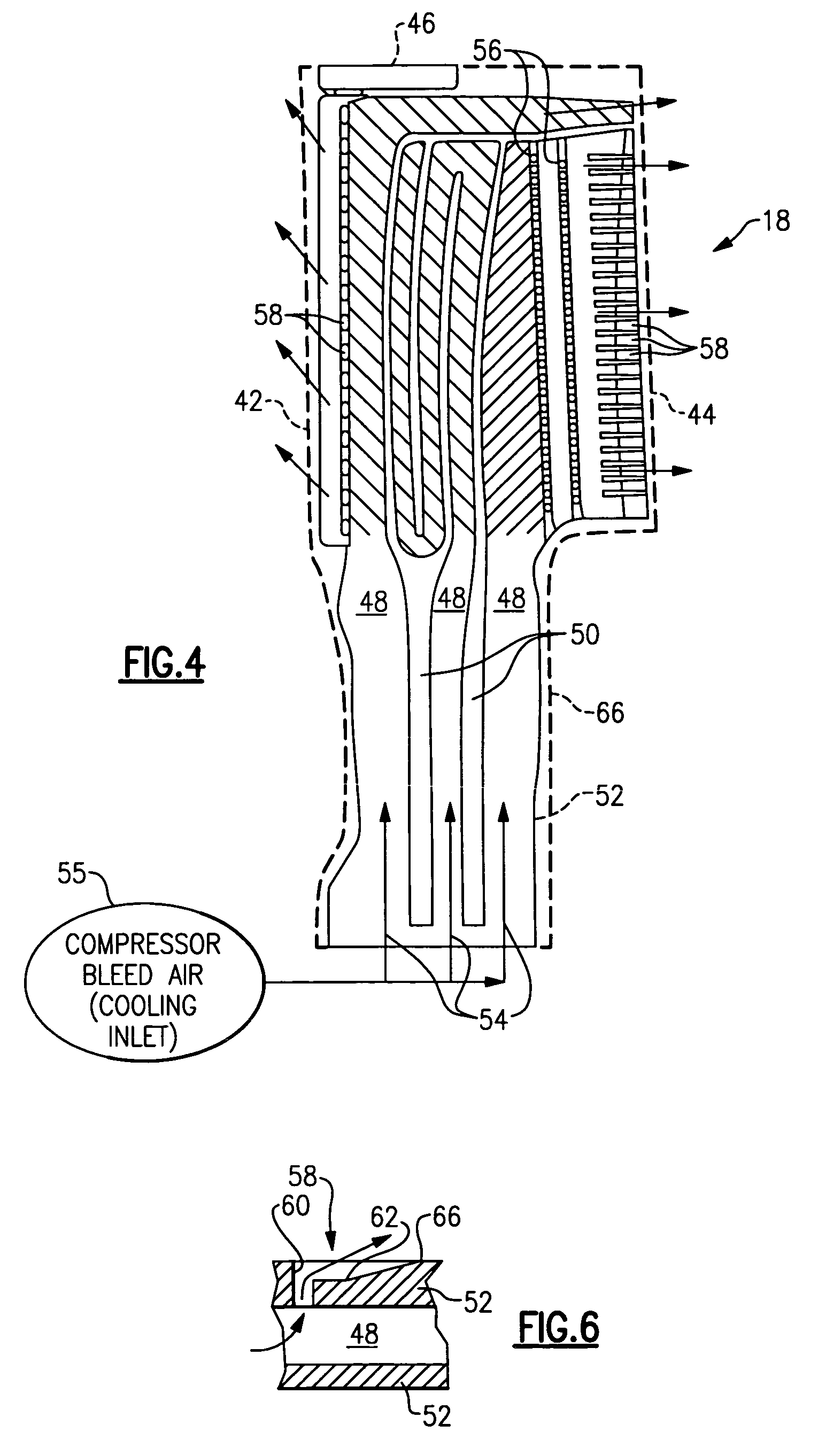
[0018]A gas turbine engine 10 is schematically shown in FIG. 1. The turbine engine 10 includes a compressor section 12, a combustor section 14, and a turbine section 16. The example turbine engine structure is illustrated as a rotor blade 18 in the example shown in FIG. 4-5B. However, it should be understood that the turbine engine structure can be any rotating or fixed component from a turbine section 16 or any other portion of a turbine engine. A turbine engine section 16 is schematically shown in FIG. 2. The turbine section 16 includes rotating structure such as rotor blades 18. The turbine section 16 also includes fixed structure such as guide and stator vanes 20, 22 and blade outer air seals 24 arranged on a case 26. These structures are well known in the art and typically include passages for providing a cooling fluid to film holes on an exterior of the structure.

[0019]Hollow turbine engine structures are typically formed using a mold 28 having two or more portions, as schemat...


PUM

PropertyMeasurementUnit
temperatureaaaaaaaaaa
structuresaaaaaaaaaa
structureaaaaaaaaaa

Abstract

A turbine engine structure is provided that includes a wall having an exterior surface defining an internal passage. A locating hole extends through the wall from the exterior surface to the passage. A film hole is recessed in the exterior surface and adjoins the locating hole. The film hole and locating hole are in communication with the passage. The locating hole is formed during the casting process in which a core is supported with a locating pin. Upon removal of the locating pin, the locating hole is formed. The locating holes can be used to determine a position of features of the structure for subsequent processing operations of the structure. For example, film holes are machined in the exterior surface, such as by an electrical discharge machining process, to intersect the locating holes.

Description

BACKGROUND OF THE INVENTION[0001]This invention relates to turbine engine structures having cooling passages and film holes.[0002]Gas turbine engines have numerous hollow structures that utilize film holes to create a boundary layer adjacent to the structure to lower the temperature of the structure. Example turbine engine structures include rotor blades, guide vanes, stator vanes, and blade outer air seals.[0003]The hollow structures are typically cast using cores that are supported within molds. The cores are typically supported by pin-like devices that leave locating holes extending from an exterior surface of the structure through a wall to the passage formed by the core once the core and pin are removed.[0004]The hollow structure typically undergoes machining operations subsequent to casting. Determining the location of the passages and other heat transfer features within the hollow structure accurately is desirable. Typically external features such as the blade tip and / or lead...

Claims


Application Information

Patent Timeline
Patent Type & Authority Applications(United States)
IPC IPC(8): B23P17/00B23P15/04B21B1/46
CPCB22C21/14F01D5/186F01D5/187F23R3/06F23R2900/03042Y10T29/49989F05D2250/232F05D2230/12Y10T29/4932Y10T29/49995Y10T29/49988F05D2230/21F01D5/20
Inventor TRINDADE, RICARDOPIETRASZKIEWICZ, EDWARD F.GARTLAND, MATHEW C.
Owner UNITED TECH CORP
Learn More