
Network for Measuring Greenhouse Gases in the Atmosphere

Active Publication Date: 2014-07-10
EARTH NETWORKS +1
View PDF2 Cites 2 Cited by
  • Summary
  • Abstract
  • Description
  • Claims
  • Application Information

AI Technical Summary

Benefits of technology

The patent describes techniques for measuring greenhouse gases in the atmosphere and calibrating devices to do so. The techniques allow for real-time, continuous measurement across a wide area. The patent also includes improvements in calibrating in-situ devices and analyzing data to determine the location of potential emissions sources and sinks. Overall, the patent provides tools for identifying and monitoring greenhouse gas sources and sinks.

Problems solved by technology

One challenge has been to accurately measure greenhouse gases in the atmosphere over a distributed geographical area to determine the location of potential sources of greenhouse gases.

Method used


Image

  • Network for Measuring Greenhouse Gases in the Atmosphere
  • Network for Measuring Greenhouse Gases in the Atmosphere
  • Network for Measuring Greenhouse Gases in the Atmosphere

Examples


Embodiment Construction

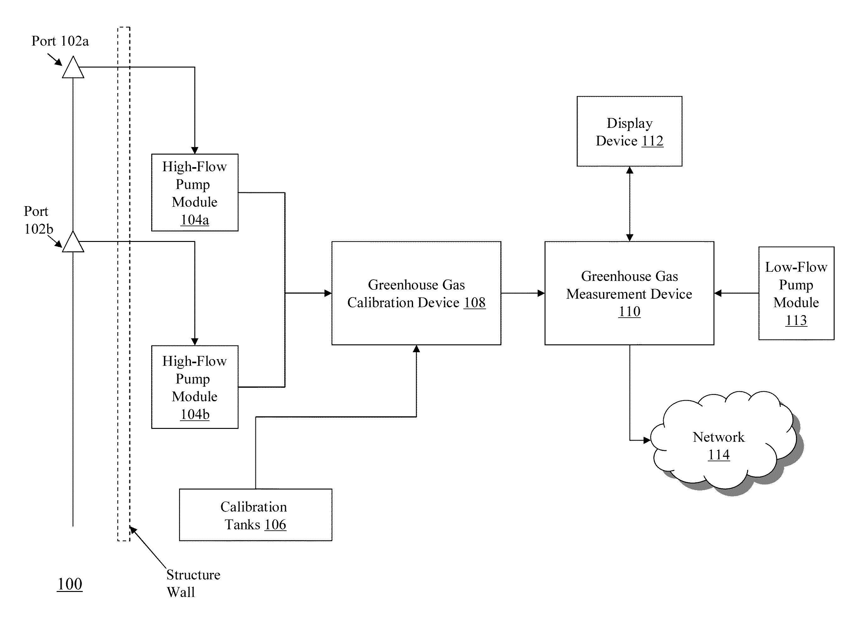
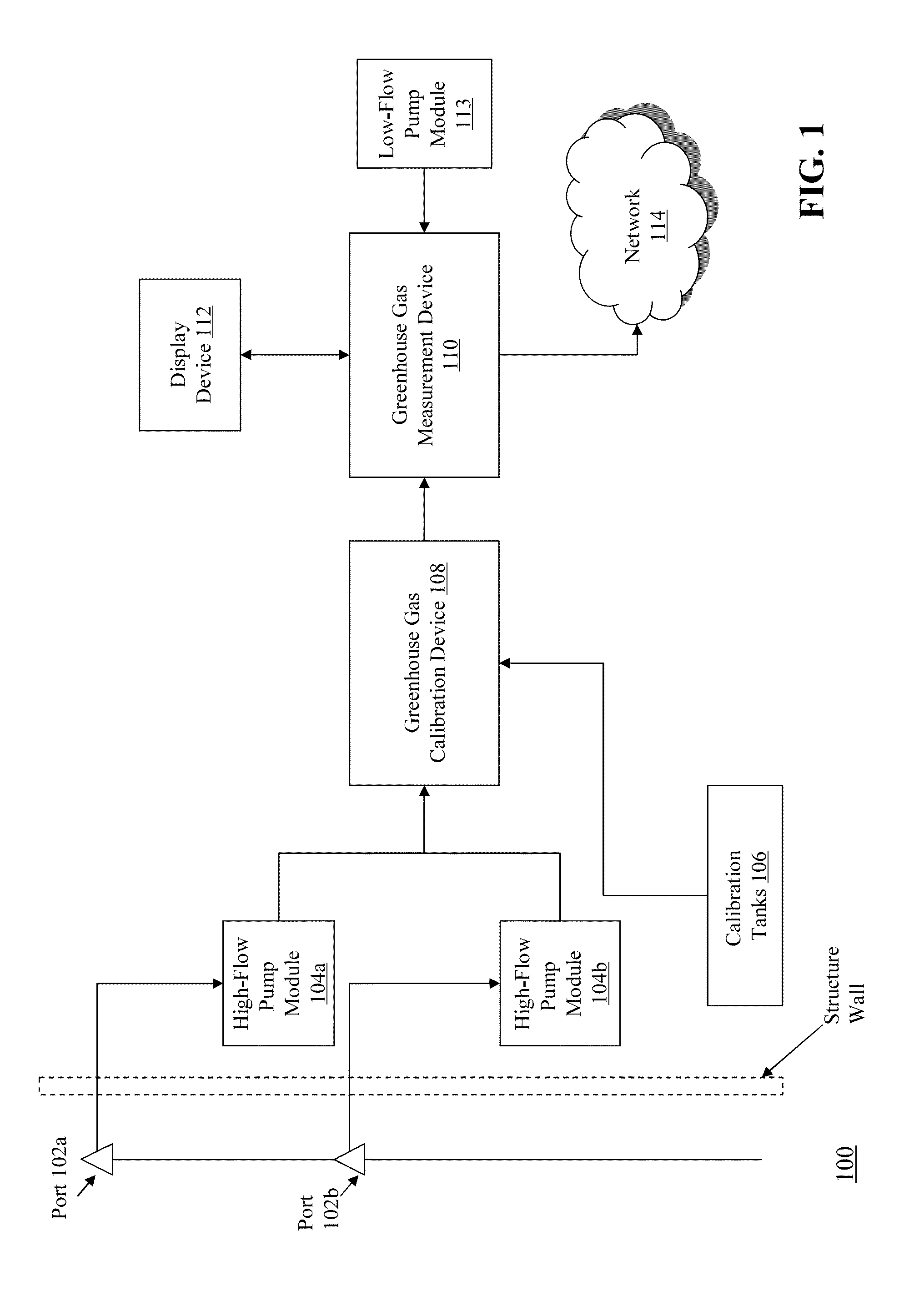
[0031]FIG. 1 is a block diagram of a system 100 for measuring greenhouse gas in the atmosphere. The system 100 includes ports 102a and 102b, high-flow pump modules 104a and 104b, calibration tanks 106, greenhouse gas calibration device 108, greenhouse gas measurement device 110, display device 112, and low-flow pump module 113. The system 100 is connected to a communications network 114.

[0032]The ports 102a and 102b are positioned in an external location, for example on a tower outside of a building or other structure that houses the remaining components of the system 100. The ports 102a and 102b sample atmospheric gas and route the sampled gas to pump modules (e.g., 104a and 104b). It should be appreciated that the amount of sampled gas can vary based on the devices used to implement the system 100. For example, in some embodiments, the measurement device 110 samples a pre-defined volume of gas according to the size of a cavity within the device 110. Based on the particular measure...


PUM


Abstract

Methods and apparatuses, including computer program products, are described for measuring greenhouse gas. A calibration device receives a first sample of atmospheric gas from a first port exposed to the earth's atmosphere. The calibration device receives a second sample of atmospheric gas from a second port exposed to the earth's atmosphere. The calibration device routes the first sample and the second sample to a measurement device for greenhouse gas analysis. The measurement device determines a characteristic of a greenhouse gas present in at least one of the first sample and the second sample. The measurement device transmits data associated with the determined characteristic of the greenhouse gas to a computing device for determining sinks and sources of the gas.

Description

FIELD OF THE INVENTION[0001]The subject matter of this application relates generally to methods and apparatuses, including computer program products, for measuring greenhouse gases in the atmosphere and determining sinks and sources of these gases.BACKGROUND OF THE INVENTION[0002]The release of greenhouse gas into the atmosphere has significant environmental and economic impact on a worldwide scale. Local, state and federal governments are under increasing pressure to monitor and regulate greenhouse gas emissions to prevent further damage to the earth's climate and environment. One challenge has been to accurately measure greenhouse gases in the atmosphere over a distributed geographical area to determine the location of potential sources of greenhouse gases.SUMMARY OF THE INVENTION[0003]In general overview, the techniques described herein are related to the measurement of greenhouse gases in the atmosphere, the calibration of devices to perform the measurement, and the determinatio...

Claims


Application Information

Patent Timeline
IPC IPC(8): G01N33/00
CPCG01N33/0004G01N33/0006
Inventor SLOOP, CHRISTOPHER DALENOVAKOVSKAIA, ELENAMARSHALL, ROBERT S.WEISS, RAY F.KEELING, RALPHWELP-SMITH, LISAPAPLAWSKY, WILLIAM J.
Owner EARTH NETWORKS
Learn More