
Projecting capacitive touch sensing device, display panel, and image display system

a capacitive touch and sensing device technology, applied in the field of projecting, can solve the problems of increasing the number of sensing axes configured within the device, increasing increasing the size etc., to reduce the manufacturing cost of the touch sensor, simplify the applied circuit, and accurately determine the location of the touch.

Active Publication Date: 2009-03-19
INNOLUX CORP
View PDF6 Cites 57 Cited by
  • Summary
  • Abstract
  • Description
  • Claims
  • Application Information

AI Technical Summary

Benefits of technology

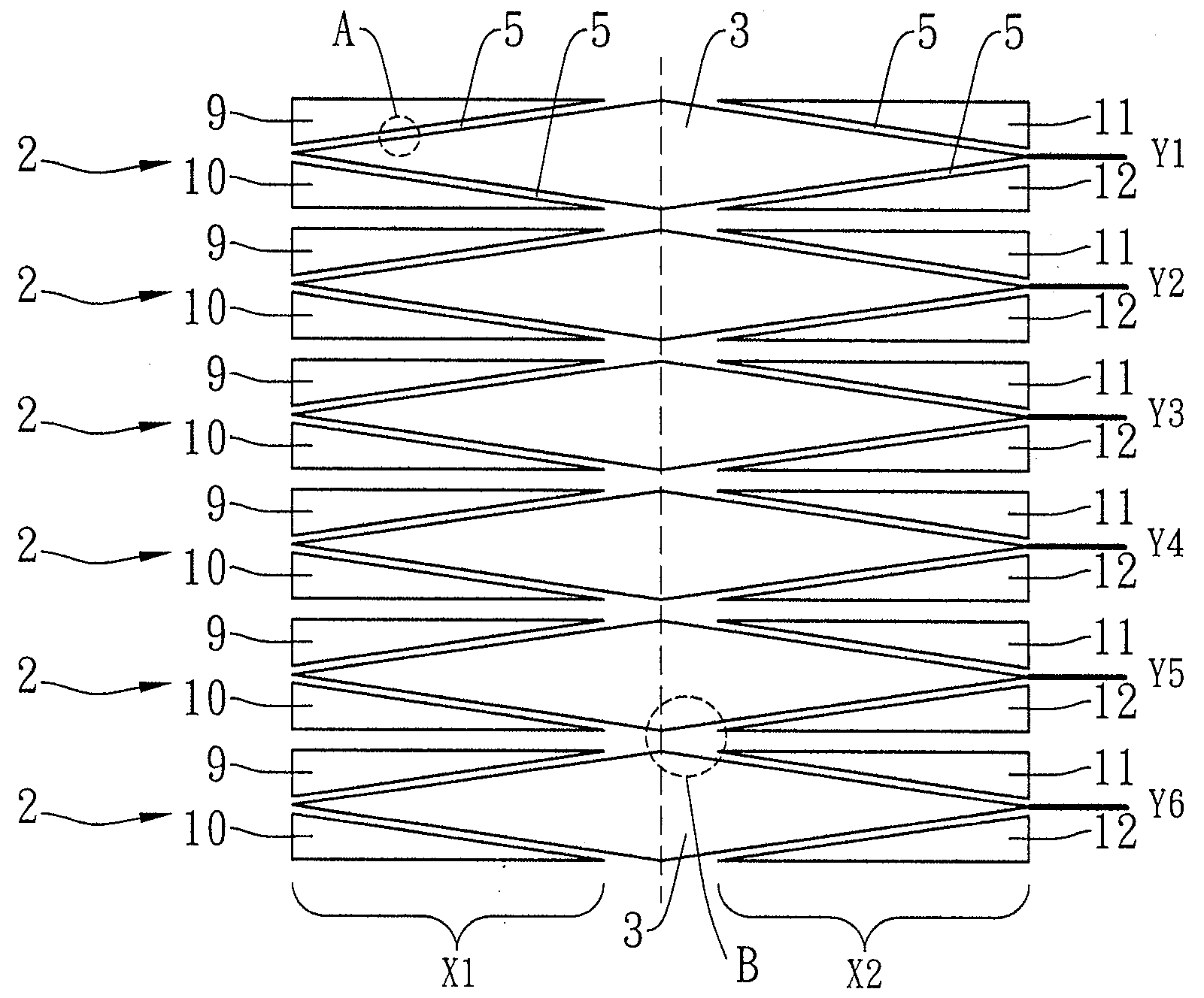
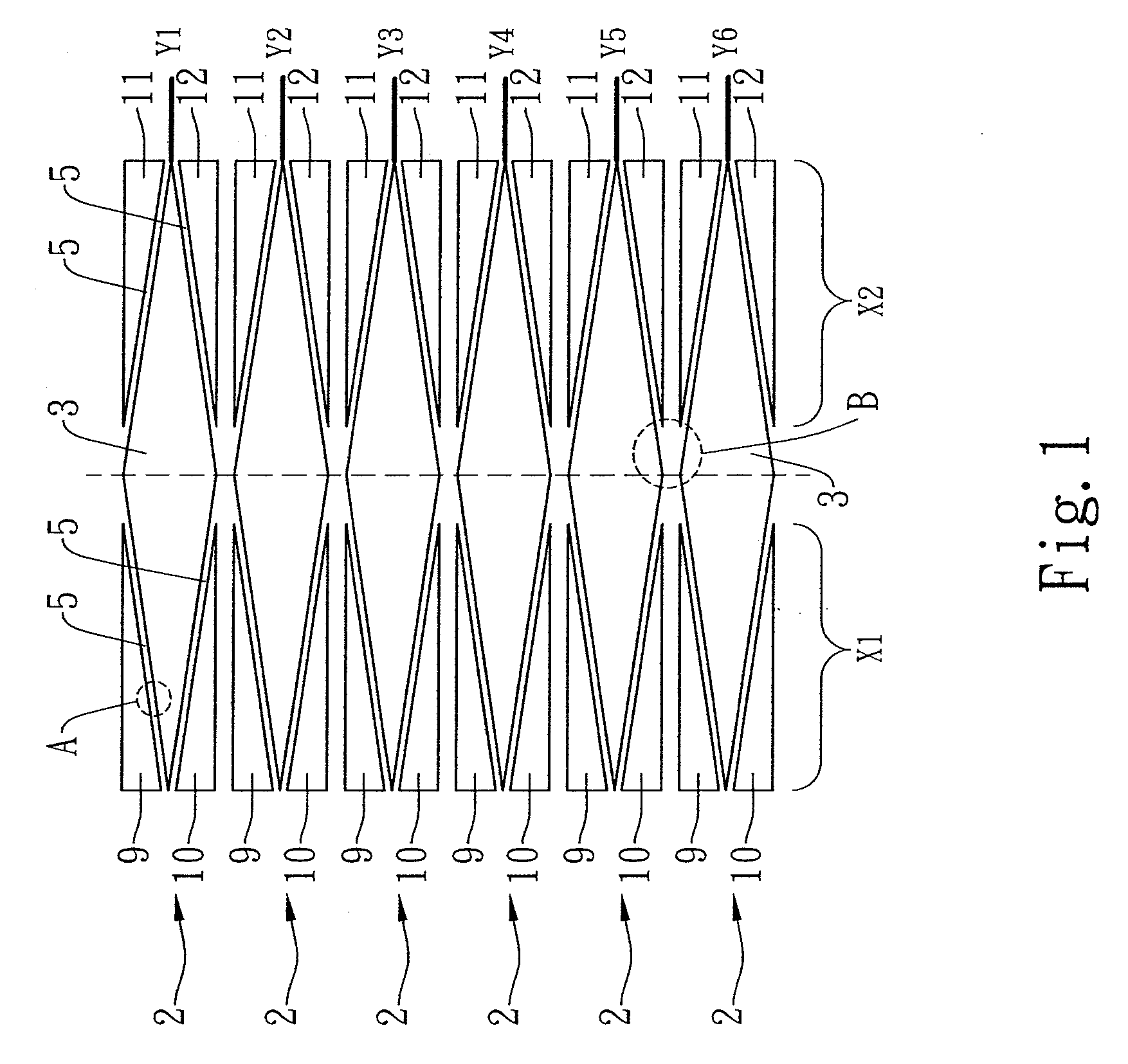
[0007]It is an object of the present invention to provide an array of rhombic-shaped first electrodes along with triangular-shaped second electrodes, wherein the first electrodes are electrically connected to first sensing axes and the second electrodes are electrically connected to second sensing axes. The present invention enables a touch sensing device to accurately determine the location of a touch, which is made by the user's finger or conductive device, with the fewest number of the first sensing axes and second sensing axes. In consequence, the present invention can reduce the manufacturing cost for the touch sensor and simplify the applied circuits within it.

Problems solved by technology

The above method has been disclosed in U.S. Pat. No. 6,535,200 entitled “Capacitive Position Sensor” and in U.S. Pat. No. 6,297,811 entitled “Projective Capacitive Touchscreen.” Nonetheless, when the number of sensor contained in a touch sensing device increases, the number of sensing axes configured within the device will increase accordingly, and the applied circuits within the device may become more complex.
In that case, the size, manufacturing cost, or packaging cost for a touch sensor, or an electronics product applying such, will increase consequently.

Method used


Image

  • Projecting capacitive touch sensing device, display panel, and image display system
  • Projecting capacitive touch sensing device, display panel, and image display system
  • Projecting capacitive touch sensing device, display panel, and image display system

Examples


first embodiment

[0017]Referring to FIG. 1, a schematic view of a projecting capacitive touch sensing according to the present invention is shown. In this embodiment, the projecting capacitive touch sensing device comprises six sensing units 2 arranged vertically, wherein the number of sensing units may be adjusted in accordance with the size of the display panel. Each sensing unit 2 comprises: a first electrode 3 made of a sensing material, which may be transparent and conductive indium tin oxide (ITO) or indium zinc oxide (IZO); a set of second electrodes including four second electrodes 9, 10, 11, and 12 disposed around the peripheral of the first electrode 3 to form a quadrate therewith, each second electrode being made of a sensing material such as transparent and conductive ITO or IZO; at least one first sensing axis (denoted as Y) electrically connected to the first electrode 3; and at least one second sensing axis (denoted as X) electrically connected to the second electrodes 9, 10, 11, and ...

second embodiment

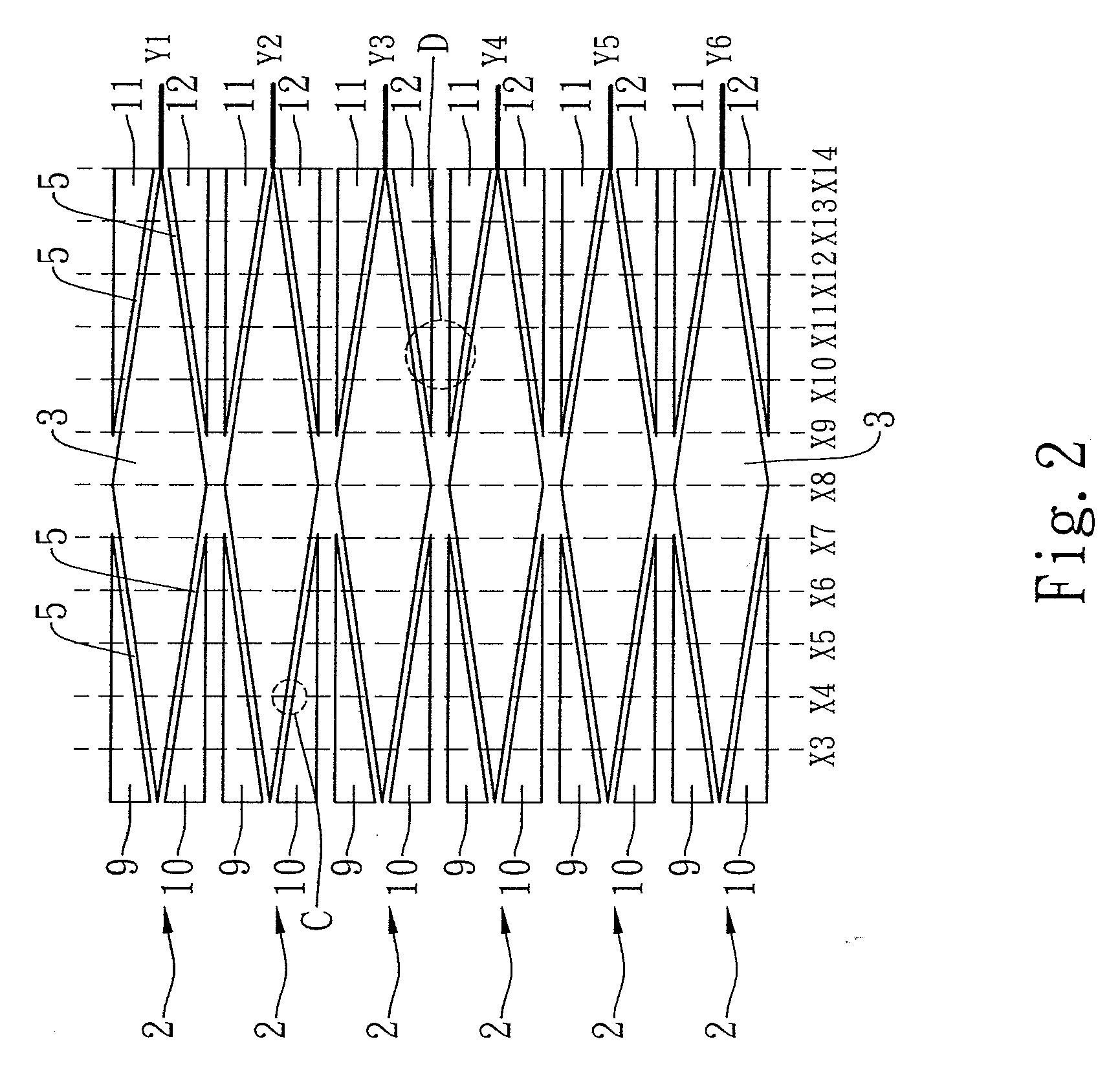
[0022]Referring to FIG. 2, a schematic view of a projecting capacitive touch sensing device according to the present invention is shown. In this embodiment, the projecting capacitive touch sensing device comprises six sensing units 2 arranged vertically, wherein the number of sensing units may be adjusted in accordance with the size of the display panel. Each sensing unit 2 comprises: a first electrode 3 made of a sensing material, which may be transparent and conductive indium tin oxide (ITO) or indium zinc oxide (IZO); a set of second electrodes including four second electrodes 9, 10, 11, and 12 disposed around the peripheral of the first electrode 3, each second electrode being made of a sensing material such as transparent and conductive ITO or IZO; at least one first sensing axis (denoted as Y) electrically connected to the first electrode 3; and at least one second sensing axis (denoted as X) electrically connected to the second electrodes 9, 10, 11, and 12.

[0023]The six first...

third embodiment

[0026]Referring to FIG. 3, a schematic view of a projecting capacitive touch sensing device according to the present invention is shown. In this embodiment, the projecting capacitive touch sensing device comprises twelve sensing units 2 arranged vertically and horizontally, wherein the number of sensing units may be adjusted in accordance with the size of the display panel. Each sensing unit 2 comprises: a first electrode 3 made of a sensing material, which may be transparent and conductive indium tin oxide (ITO) or indium zinc oxide (IZO); a set of second electrodes including four second electrodes 9, 10, 11, and 12 disposed around the peripheral of the first electrode 3, each second electrode being made of a sensing material such as transparent and conductive ITO or IZO; at least one first sensing axis (denoted as Y) electrically is connected to the first electrode 3; and at least one second sensing axis (denoted as X) is electrically connected to the second electrodes 9, 10, 11, ...


PUM


Abstract

The present invention relates to a projecting capacitive touch sensing device, display panel, and image display system. The projecting capacitive touch sensing comprises an array of a plurality of sensing units, each sensing unit including: a first electrode made of a sensing material, at least one second electrode made of a sensing material and being disposed around the peripheral of the first electrode, at least one first sensing axis electrically connected to the first electrode, and at least one second sensing axis electrically connected to the second electrodes. The first electrode is quadrangle, while the second electrodes are triangular-shaped. The first electrode and the plurality of second electrodes are arranged to form a rectangular, and a non-sensing area is defined between the first electrode and the second electrodes.

Description

BACKGROUND OF THE INVENTION[0001]1. Field of the Invention[0002]The present invention relates to a projecting capacitive touch sensing device, display panel, and image display system. More particularly, the present invention relates to a projecting capacitive touch sensing device, display panel, and image display system that can be integrated into an electronic device.[0003]2. Description of the Related Art[0004]Touch sensing technologies are upgrading constantly in recent years, and the improved quality and functionality of related products make the applications of touch sensing prodwucts even more commonplace. Touch sensing device are widely used in consumer electronics nowadays, such as mobile phones, digital cameras, PDAs, electronic dictionaries, notebook computers, desktop computers, televisions, GPS receivers, automotive displays, aircraft displays, digital photo frames, portable DVD players, etc.[0005]In brief, the work of a conventional touch sensing can be described as fol...

Claims


Application Information

Patent Timeline
Patent Type & Authority Applications(United States)
IPC IPC(8): G06F3/041
CPCG06F3/044G06F3/0448
Inventor LIN, WEI CHENGYANG, KAI CHIEHHSUEH, FU YUANCHANG, TING KUO
Owner INNOLUX CORP
Learn More