Light Ballistic Protection As Building Elements

a technology of building elements and ballistic protection, applied in the direction of protective equipment, weapons, armour, etc., can solve the problems of not protecting against projectiles with a hard core, armor-breaking ammunition, soldiers and civilians being injured, etc., to facilitate mutual movement and maximize the energy dissipation of objects or their fragments

Inactive Publication Date: 2008-01-10
PROTAURIUS
View PDF20 Cites 14 Cited by
  • Summary
  • Abstract
  • Description
  • Claims
  • Application Information

AI Technical Summary

Benefits of technology

[0038] According to another embodiment of the invention the shape of a plurality of the granules in the intermediate layer is substantially similar to a symmetrical or asymmetr...

Problems solved by technology

Even mobile protections with similar function have been produced since scatter damages and direct hits of projectiles have been and still is the foremost cause to soldiers and civilians being injured.
However, the development has proceeded and today one focuses mainly on developing light soft protections that are adapted for soldiers and do not reduce the mobility.
The disadvantages are that they do not protect against projectiles with a hard core, so called armor-breaking ammunition, unless the thickness of the protection is considerably increased.
However, this affects the weight in a negative way, b) fiber composites that protects by a high inter-laminar breaking tenacity.
The disadvantages with these protections are that they do not protect against projectiles with a hard core, and that they are usually based on fairly expensive fiber materials manufactured by for example 3D-weaving, 3D-braiding, stitch bonding (stitching) or short-fiber insertion.
In addition, effective protections usually demand combin...

Method used


Image

  • Light Ballistic Protection As Building Elements
  • Light Ballistic Protection As Building Elements
  • Light Ballistic Protection As Building Elements

Examples


Embodiment Construction

[0062] It has long been a desire to be able to design a ballistic protection against scatter, ricochets and other projectiles, which at the same time is easy to handle with a reasonable weight. Consequently, the main task of the invention is to design a robust deaccelerating protection for nonjacket, jacket and full jacket projectiles alternatively tracer projectiles and hand grenades that, by its comparably low mass, is easy to assemble or move if so required.

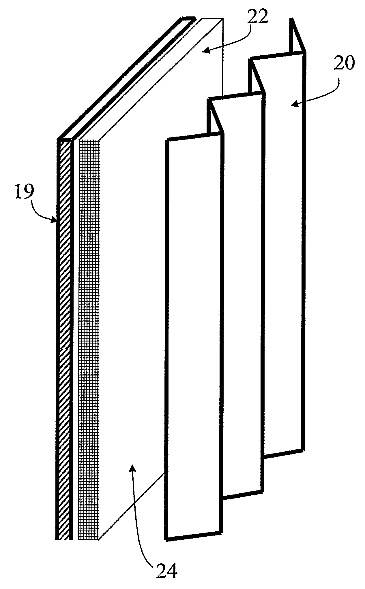
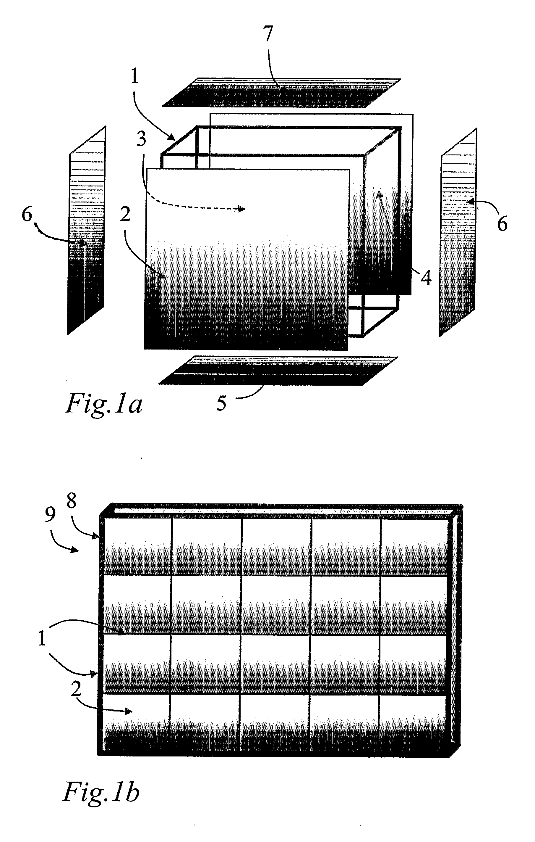
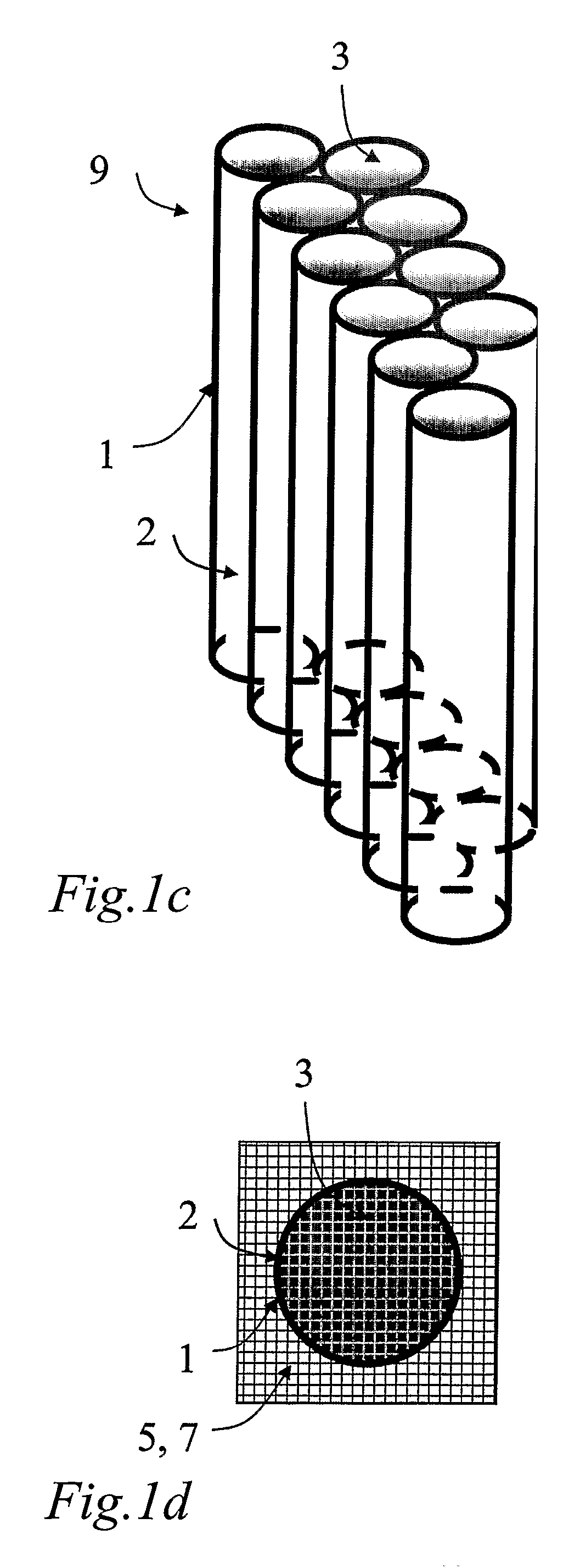
[0063] According to the invention the design is characterized in that the ballistic protection can be shaped in accordance with FIG. 1a as a sub-element with a frame 1 that carries a front panel 2 through which the projectile passes, and at least an intermediate layer 3 which together with the front panel forces the projectile to deaccelerate, and a rear panel 4 that finally stops the projectile. The other panels are the bottom panel 5, two side panels 6 and an upper panel 7, which are designed in such a way that the protecti...


PUM


Abstract

The present invention concerns a ballistic protection against objects such as projectiles from fire arms, alternatively scatter from for example hand grenades. The protection comprises an enclosure (1, 2, 4, 5, 6, 7, 9) adapted so that the object (10) can penetrate the enclosure (1, 2, 4, 5, 6, 7, 9) in at least one area (2); at least one intermediate layer (3) comprising granules (27) arranged within the enclosure (1, 2, 4, 5, 6, 7, 9), which intermediate layer (3) and enclosure (1, 2, 4, 5, 6, 7, 9) are arranged to deaccelerate said object (10). The invention is further characterized in that: the granules (27) are movable arranged with respect to each other; the space in the intermediate layer (3) that is not occupied by granules (27) is filled by a gas medium to enable contact between adjacent granules (27); the granules (27) have mechanical properties so that a granule (27) is crushed and spread in the intermediate layer (3) when it is hit by an object (10), at the same time as adjacent granules (27) are subjected to impulses with a subsequent energy dissipation so that the object and fragments thereof remains in the protection with a reduced risk for ricochets.

Description

TECHNICAL AREA [0001] The present invention concerns a ballistic protection against objects such as projectiles from fire arms; alternatively scatter from for example hand grenades. [0002] The invention comprises flexible and movable protection walls, which can be modularized depending on the desired protection. The protection will find use as permanent as well as movable protection shelters, sub-component in bullet proof containers and movable command centers and also as protective floors and side protection in transport planes and vehicles as well as protective space delimiters in hazardous workrooms and as construction elements in larger building structures. PRIOR ART [0003] It has been known for a long time that ballistic protection and walls of different kinds have found their natural form for different fortress constructions. These constructions were stationary, but temporary and semi-stationary protections have also been manufactured. Even mobile protections with similar func...

Claims


Application Information

Patent Timeline
IPC IPC(8): F41H5/04F41H
CPCF41H5/0492F41H5/04
Inventor MAGNUSSON, BJORNWALLERMAN, LARS-OLOVKARLSTROM, ANDERSJACOBSSON, LARSRHEDIN, HENRIC
Owner PROTAURIUS
Why Eureka
Try Eureka