
Image forming apparatus

Active Publication Date: 2008-01-10
RICOH KK
View PDF12 Cites 39 Cited by
  • Summary
  • Abstract
  • Description
  • Claims
  • Application Information

AI Technical Summary

Benefits of technology

[0008] In view of the foregoing, the present invention is directed to provide an image forming apparatus that satisfies two competing demands: facilitating attachment / removal of a unit; and ensuring positional accuracy thereof.
[0023] According to embodiments of the present invention, since the second unit is removable from the rotatable part, maintenance of components inside the apparatus main body is easily carried out. Moreover, since the direction in which the unit to be removed is moved and the attaching / removing direction are the same, maintenance work is facilitated.
[0024] Embodiments of the present invention make it possible to remove the second unit with ease and attach the second unit with high positional accuracy. If the second unit includes the transport unit, a paper jam is easily resolved.

Problems solved by technology

In development of image forming apparatuses, downsizing of the apparatuses is one important issue.
An image forming apparatus of this type has a problem in that, when carrying out maintenance or replacement of an internal unit disposed inside the apparatus, the unit on the inner surface of the door often impedes maintenance or replacement of the internal unit.
However, if the unit is made easily attachable and detachable, the unit is likely to be attached with low positional accuracy.

Method used


Image

  • Image forming apparatus
  • Image forming apparatus
  • Image forming apparatus

Examples


Embodiment Construction

[0034] The following describes preferred embodiments of the present invention with reference to the accompanying drawings.

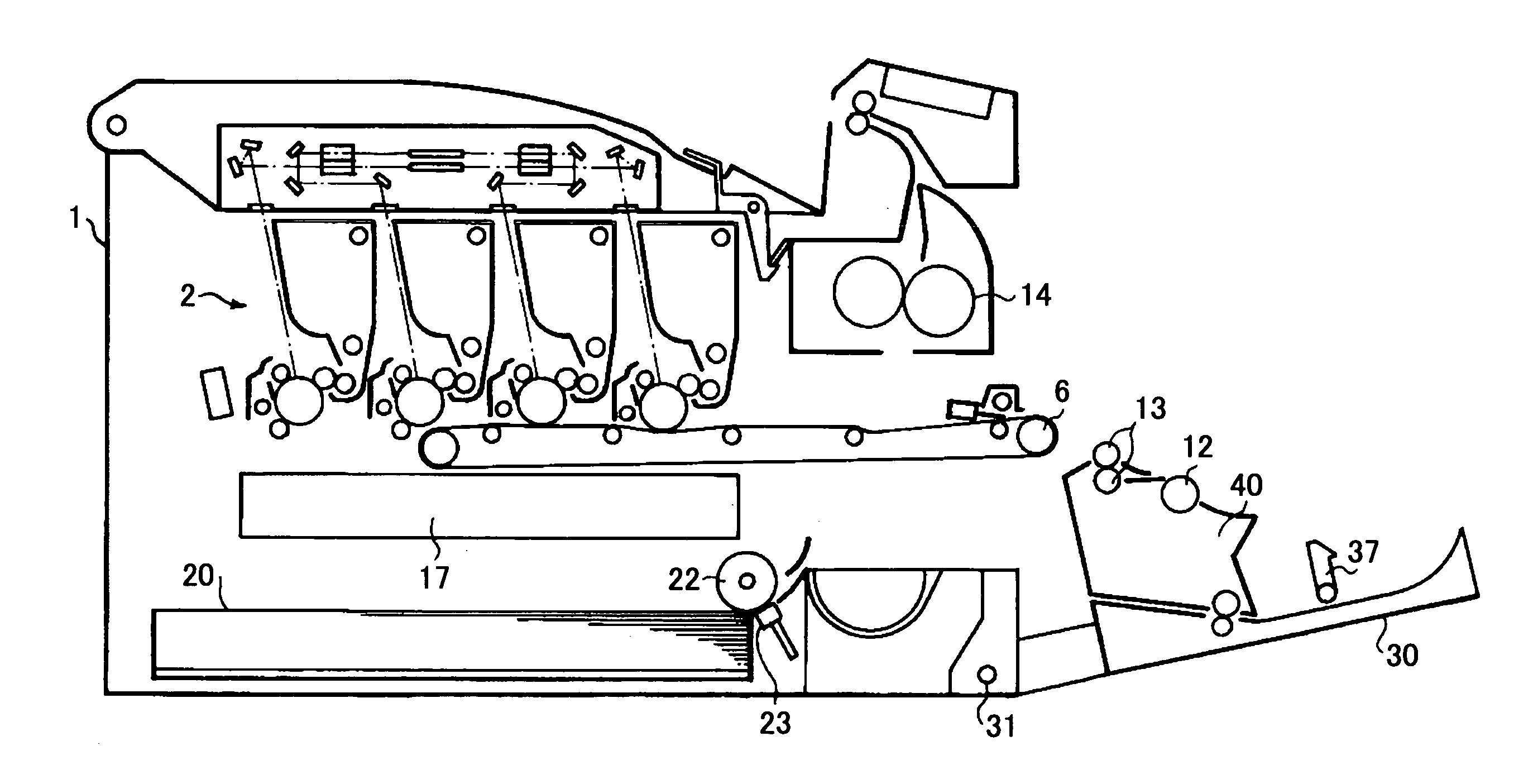
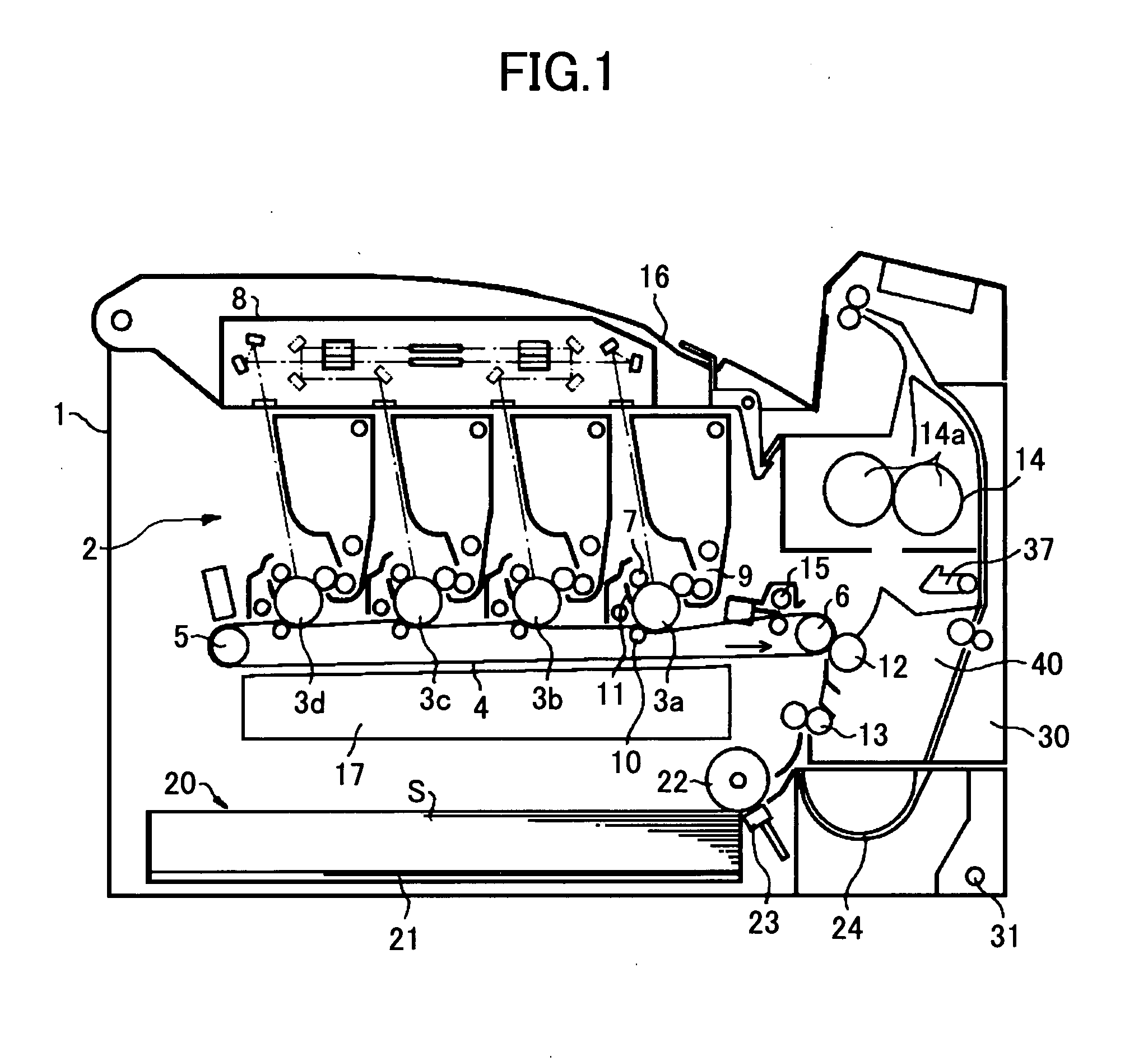
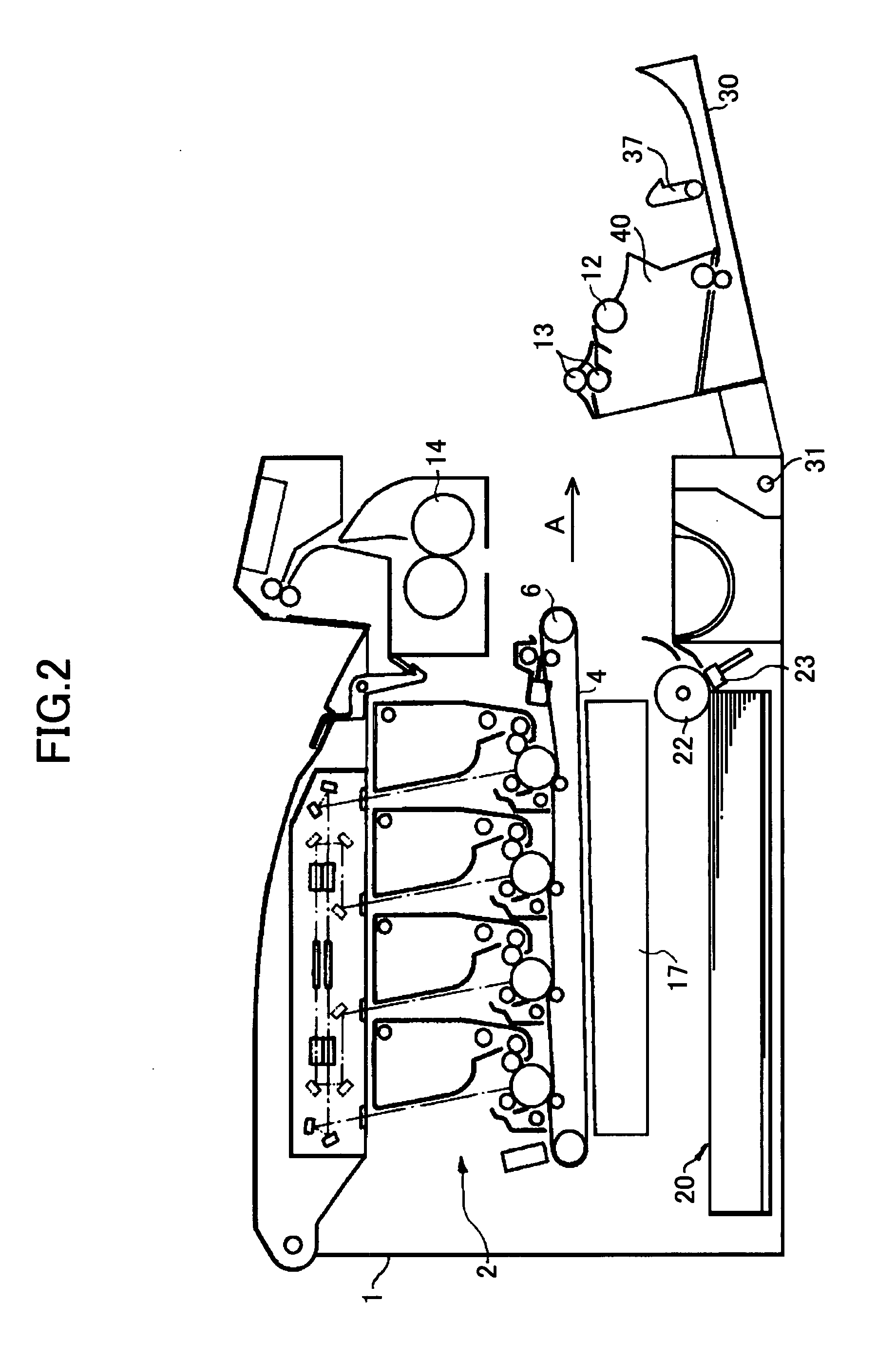
[0035]FIG. 1 is a cut-away side view schematically showing an image forming apparatus according to an embodiment of the present invention.

[0036] With reference to FIG. 1, the image forming apparatus of this embodiment is a tandem type color image forming apparatus that includes an image forming section 2 in the center of an apparatus main body 1 and, under the image forming section 2, a sheet feed section 20 for feeding sheets on which images are to be formed in the image forming section 2.

[0037] The image forming section 2 includes drum-type photoreceptors 3a, 3b, 3c, and 3d (hereinafter also referred to as photoreceptors 3) as image carriers, on which toner images are formed in different colors. In the illustrated example, a yellow toner image, a magenta toner image, a cyan toner image, and a black toner image are formed on the surfaces of the photoreceptors...


PUM


Abstract

An image forming apparatus is disclosed. The image forming apparatus includes an apparatus main body, a first unit to be attached inside the apparatus main body, a rotatable part attached to the apparatus main body and rotatable between an open position for opening the apparatus main body and a closed position for closing the apparatus main body, and a second unit removably attached to the rotatable part. When the rotatable part is rotated from the closed position to the open position, the first unit is allowed to be attached to or removed from the apparatus main body by being moved horizontally. By removing the second unit from the rotatable part, the first unit is attached to or removed from the apparatus main body without coming into contact with the second unit.

Description

BACKGROUND OF THE INVENTION [0001] 1. Field of the Invention [0002] The present invention relates to an image forming apparatus including a printer, a facsimile machine, a copier, and a multifunction machine having functions of at least two of these machines. [0003] 2. Description of the Related Art [0004]<Patent Document 1> Japanese Patent Laid-Open Publication No. 2004-205534 [0005] In development of image forming apparatuses, downsizing of the apparatuses is one important issue. For downsizing the apparatuses, component parts need to be arranged with high space efficiency while reducing excess space inside the apparatus. Patent Document 1 discloses an image forming apparatus that includes an exterior panel of an apparatus main body configured as a rotatable door and, on the inner surface of the door is mounted a unit such as a transport unit. [0006] An image forming apparatus of this type has a problem in that, when carrying out maintenance or replacement of an internal uni...

Claims


Application Information

Patent Timeline
IPC IPC(8): B41F13/008
CPCB41J11/006B41J29/02G03G21/168G03G21/1633G03G2221/1642
Inventor OHKUBO, YASUHIDEFUJIWARA, HIROSHINANNO, SHIGEOKIMURA, IPPEIOHTA, YOSHIHIDEYAMAZAKI, TOMOYOSHITAKAHIRA, MASAFUMIHONDA, HARUYUKI
Owner RICOH KK
Learn More