Power Steering Device and Method of Controlling the Power Steering Device

a technology of power steering and power steering device, which is applied in the direction of steering initiation, instruments, vessel construction, etc., can solve the problems of large steering force to be produced by the driver, insufficient steering assist force, and inability to make positive steering assist during manual steering mod

Inactive Publication Date: 2008-01-10
HITACHI LTD
View PDF6 Cites 26 Cited by
  • Summary
  • Abstract
  • Description
  • Claims
  • Application Information

AI Technical Summary

Benefits of technology

[0014]According to the invention as defined in claim 2, it is possible to detect a failure in the first hydraulic pressure supply means by virtue of

Problems solved by technology

In the power steering system disclosed in the previously-described Japanese document, the system can be shifted to the manual steering mode in presence of a system failure, for example, in presence of a reversible-pump failure, however, a positive steering assist cannot be made during the manual steering mode.
This means a large magnitude of steering force to be produced by the d

Method used


Image

  • Power Steering Device and Method of Controlling the Power Steering Device
  • Power Steering Device and Method of Controlling the Power Steering Device
  • Power Steering Device and Method of Controlling the Power Steering Device

Examples


first embodiment

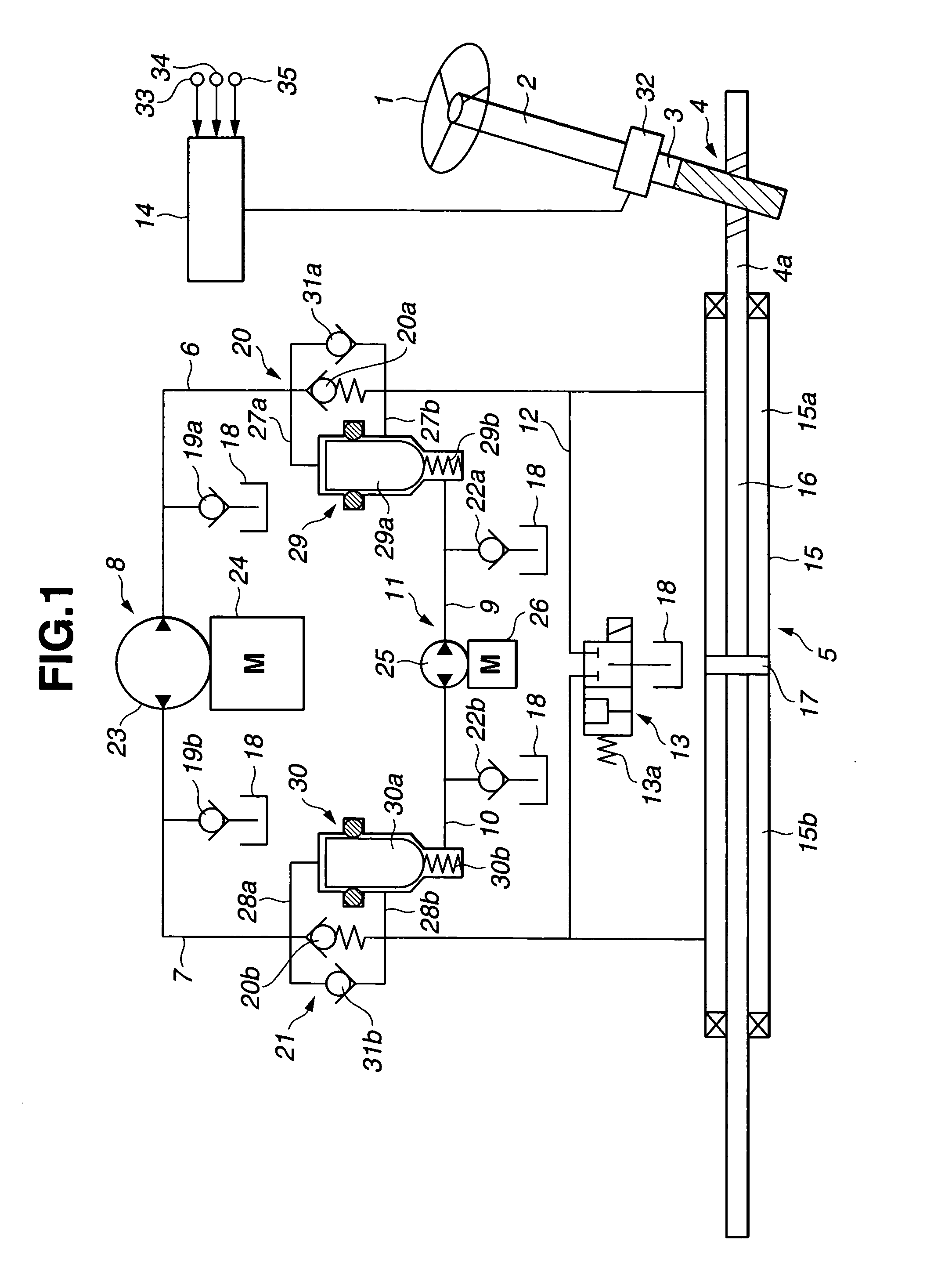
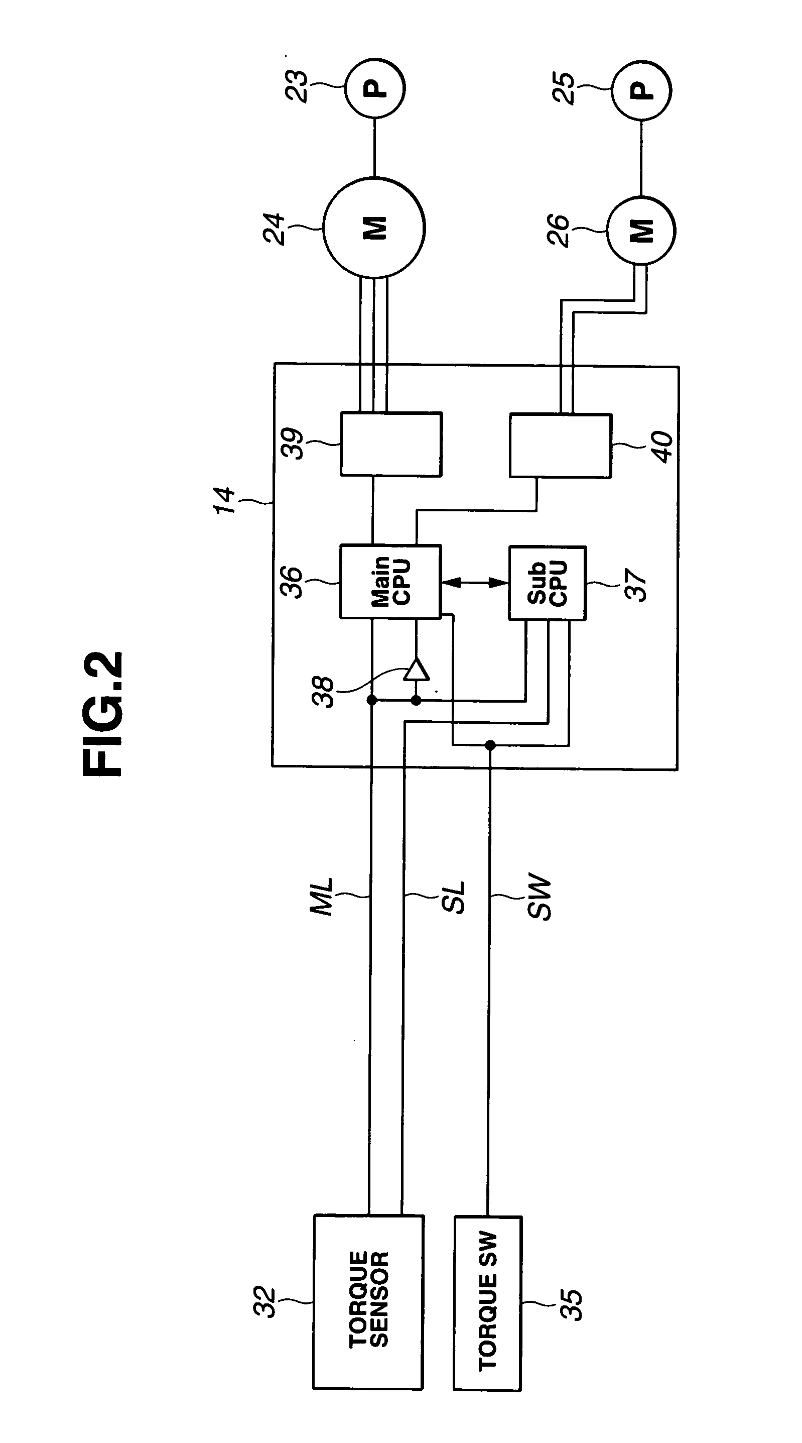
[0053]FIG. 1 schematically shows the power steering system of the first embodiment. The system of the first embodiment is mainly comprised of a steering shaft 2 to which a steering wheel 1 is fixedly connected, a rack-and-pinion mechanism 4 serving as a steering mechanism (a steering gear mechanism) installed on an output shaft 3 linked to a lower end of steering shaft 2, a hydraulic power cylinder 5 provided to render assistance to a driver's operating force applied to the steering wheel, a first hydraulic pressure supply mechanism 8 serving as the first hydraulic pressure supply means for selectively supplying working fluid pressure to hydraulic power cylinder 5 via either one of first and second fluid passages 6 and 7, a second hydraulic pressure supply mechanism 11 arranged parallel to first hydraulic pressure supply mechanism 8 and serving as the second hydraulic pressure supply means for selectively supplying working fluid pressure to hydraulic power cylinder 5 via either one ...

second embodiment

[0177]Referring now to FIG. 15, there is shown the system of the second embodiment. The second embodiment is different from the first embodiment in that, in the second embodiment, the capacities of second electric motor 26 and second trochoid pump 25 of second hydraulic pressure supply mechanism 11 are set to the same capacities as those of first hydraulic pressure supply mechanism 8.

[0178]Second hydraulic pressure supply mechanism 11 of the second embodiment is constructed in a manner so as to operate together with first hydraulic pressure supply mechanism 8 during operation as well as during a failure in the first hydraulic pressure supply mechanism. The sum of maximum discharge capacities of first and second hydraulic pressure supply mechanisms 8 and 11 of the second embodiment is set to be substantially identical to the maximum discharge capacity of first hydraulic pressure supply mechanism 8 of the first embodiment. The discharge capacity of each of the first and second hydraul...

third embodiment

[0185]Referring now to FIG. 17, there is shown the system of the third embodiment, wherein communication passage 12 and fail-safe valve 13 are eliminated.

[0186]Therefore, when first and second hydraulic pressure supply mechanisms 8 and 11 are both failed, it is impossible to provide a fail-safe valve function. This leads to the problem of a great driver's operating load on steering wheel 1, but realizes greatly-reduced production costs.

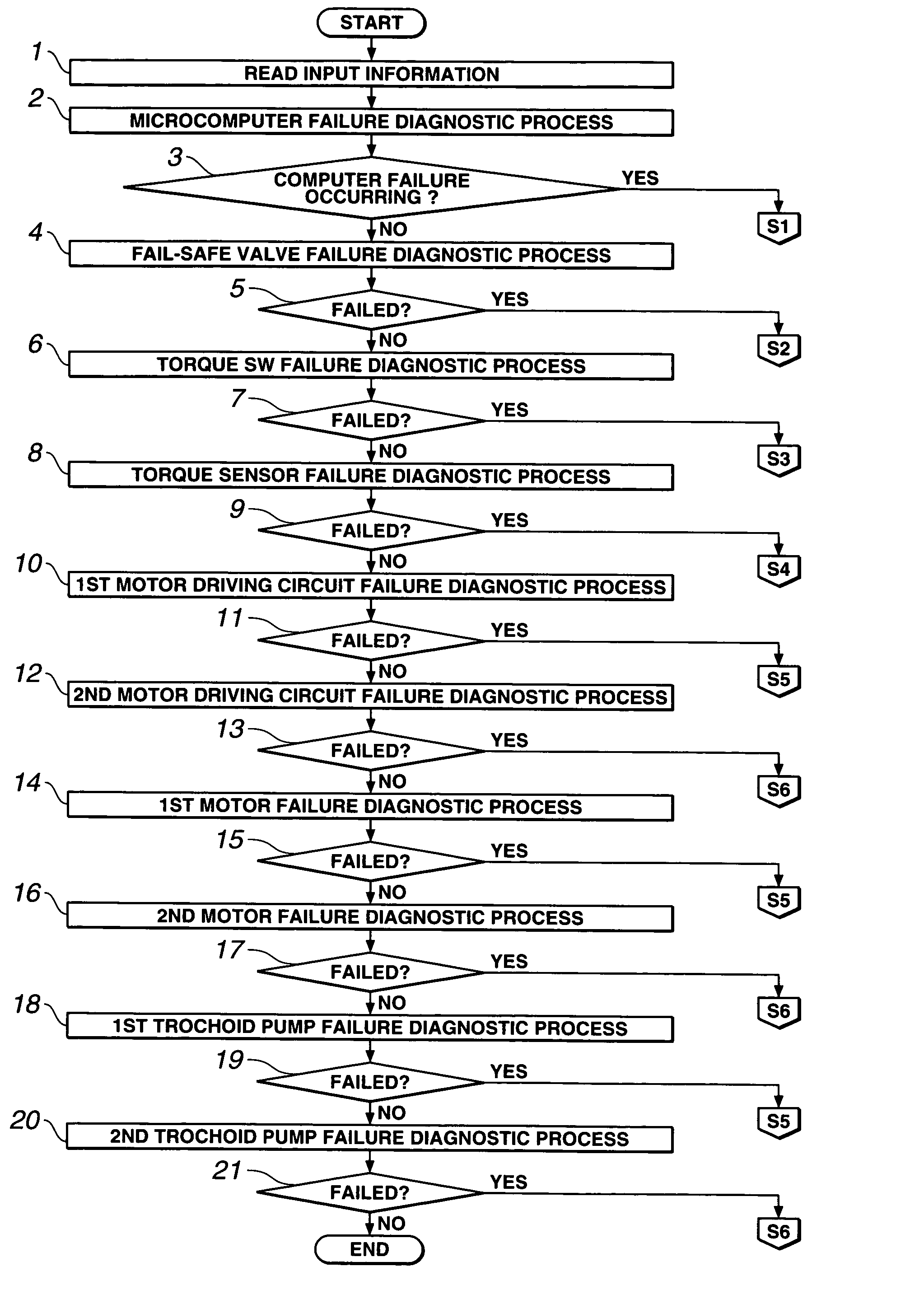
[0187]The method of failure detection performed during a system failure, such as a failure in at least one of equipments constructing the power steering system of the third embodiment, is identical to that of the first embodiment. In the system of the third embodiment the fail-safe valve is eliminated and therefore the failure-detection method (the other failure-detecting stages) except the first stage S1 is applied to the third embodiment.


PUM


Abstract

A steering system includes a hydraulic power cylinder 5 that assists a steering force of a rack-and-pinion mechanism 4, and a first hydraulic pressure supply mechanism 8 having a first trochoid pump 23 selectively supplying hydraulic pressure to two hydraulic pressure chambers 15a and 15b of the hydraulic power cylinder via first and second fluid passages 6 and 7, and a first electric motor 24 for the first trochoid pump. When the first hydraulic pressure supply mechanism becomes failed, a second hydraulic pressure supply mechanism 11 is operated responsively to a command signal from a control unit 14 to selectively supply hydraulic pressure via third and fourth fluid passages to either one of the hydraulic pressure chambers.
Thus, it is possible to positively apply a steering assist force by means of the second hydraulic pressure supply mechanism 11, thereby reducing a driver's operating force applied to a steering wheel.

Description

TECHNICAL FIELD[0001]The present invention relates to a power steering device (a power steering system) enabling steering assist force application by operating a hydraulic power cylinder responsively to the magnitude of steering torque, which torque is output from a steering mechanism of an automotive vehicle, and specifically to a control method of the power steering system.BACKGROUND ART[0002]A power steering system disclosed in the following patent publication designated by “Document 1” is generally known as this type of power steering system.[0003]The power steering system disclosed in this document is comprised of a steering shaft mounting thereon a steering wheel, an output shaft linked to the lower end of the steering shaft, a rack-and-pinion mechanism installed on the lower end of the output shaft for steering of steered road wheels, a hydraulic power cylinder linked to the rack of the rack-and-pinion mechanism, and a reversible pump provided to selectively supplying working...

Claims


Application Information

Patent Timeline
IPC IPC(8): B62D5/00B62D6/00B62D5/065B62D5/07B62D5/30B62D101/00B62D113/00B62D119/00B62D127/00B62D137/00
CPCB62D5/0481B62D5/30B62D5/065B62D5/06B62D5/07
Inventor SASAKI, MITSUOYOKOTA, TADAHARUSAKAKI, TOSHIMITSUHIRAMOTO, MICHIYA
Owner HITACHI LTD
Why Eureka
Try Eureka