Radio module
a radio module and antenna technology, applied in the direction of antennas, antenna details, elongated active element feed, etc., can solve the problems of increasing the size and cost of the terminal, reducing the impedance and bandwidth, etc., and achieve the effect of widening the bandwidth without increasing the size of the terminal
- Summary
- Abstract
- Description
- Claims
- Application Information
AI Technical Summary
Benefits of technology
Problems solved by technology
Method used
Image
Examples
first embodiment
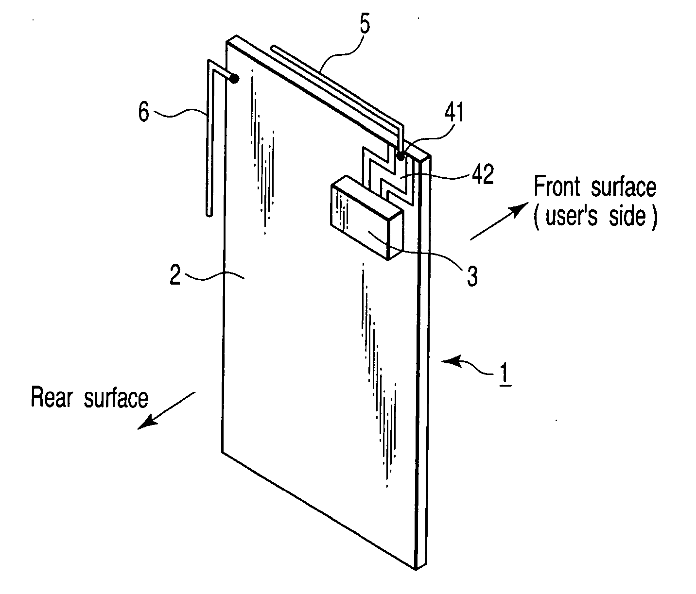
[0054]FIG. 1 is a perspective view showing the arrangement of a radio module for a portable terminal according to the first embodiment of the present invention.
[0055] The radio module is accommodated between the front cover and rear case (both not shown) of a housing of the portable terminal. In this accommodation state, a “front surface” side shown in FIG. 1 is set as a front cover side, i.e., the side facing a user's head during speech communication, and a “rear surface” side shown in FIG. 1 is set as a rear case side.
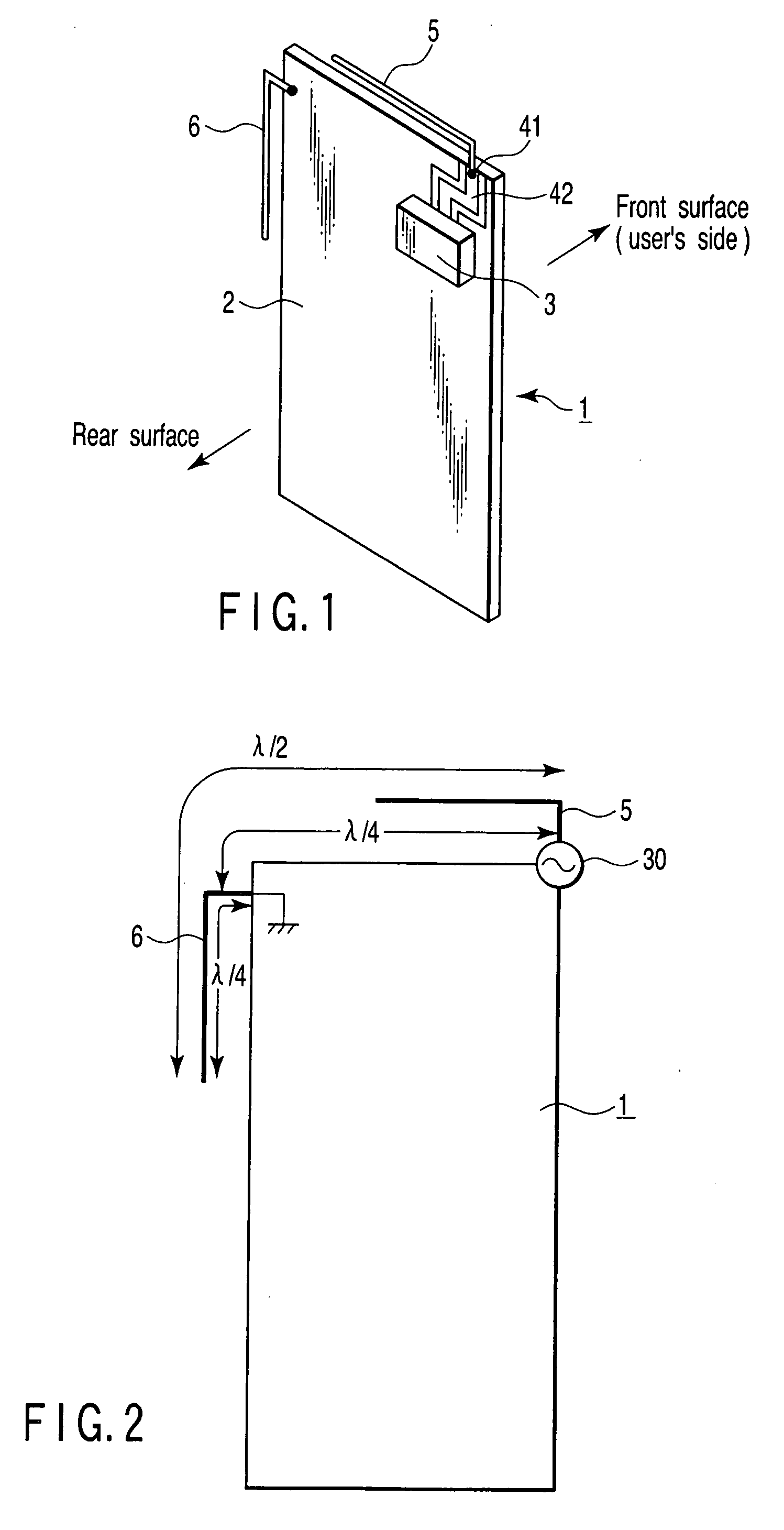
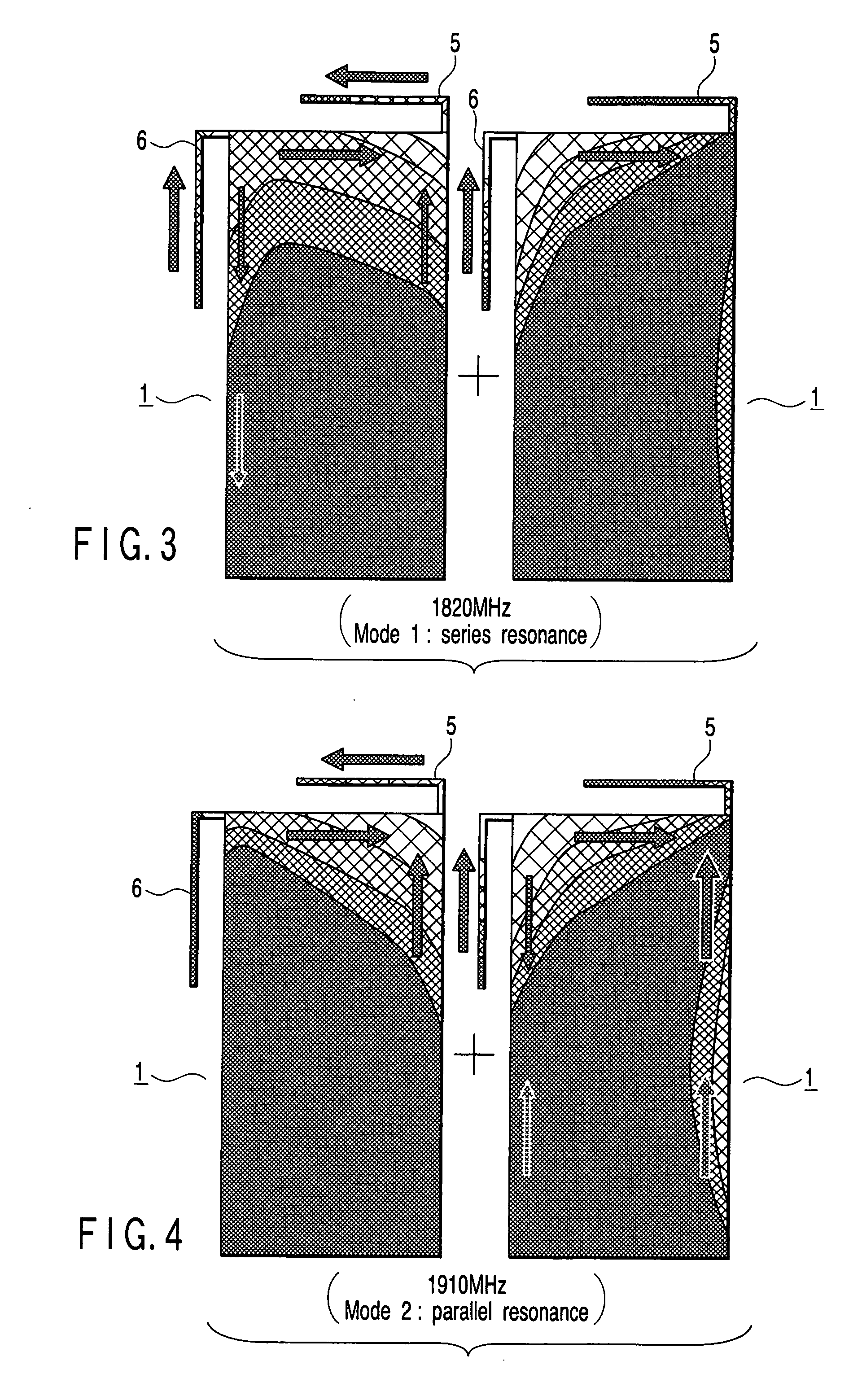
[0056] The radio module includes a circuit board 1. The circuit board 1 comprises a double-sided printed wiring board having printed wiring patterns on the front and rear surfaces, and a radio circuit 3 is mounted on the rear surface. Additionally., an antenna connection terminal 41 and a signal line pattern 42 which connects this antenna connection terminal with the radio circuit 3 are formed on the rear surface of the circuit board 1, and an antenna 5 is connecte...
second embodiment
[0069] According to the second embodiment of the present invention, in a radio module such as a radio module installed in a foldable portable terminal in which two circuit board units are connected via a flexible cable or thin coaxial cable, a conductor is grounded on a radiation of a radio frequency signal generation side of the circuit board unit on which a radio circuit and an antenna are mounted, on the extension line of the position of a connector of the cable from the viewpoint of a feed point.
[0070]FIG. 13 is a perspective view showing the arrangement of the radio module according to the second embodiment of the present invention. Note that the same reference numbers as shown in FIG. 1 denote the same parts in FIG. 13. In the radio module according to this embodiment, a first circuit board 1 accommodated in a lower housing and a second circuit board 7 accommodated in an upper housing are connected to each other via a cable 11 and connectors 9 and 10. The connector 9 is locat...
third embodiment
[0080] According to the third embodiment of the present invention, a conductor 6 is grounded on a ground pattern 2 via an impedance adjustment circuit.
[0081]FIG. 20 is a perspective view showing the arrangement of a radio module according to the third embodiment of the present invention. Note that the same reference numbers as in FIG. 1 denote the same parts in FIG. 20, and a detailed description thereof will be omitted. An impedance adjustment circuit 12 is mounted on a radiation of a radio frequency signal generation side of a circuit board 1, at a position spaced apart by a quarter-wavelength of a radio-frequency signal from a feed point. The conductor 6 is connected to the ground pattern 2 via the impedance adjustment circuit 12.
(1) Example 1
[0082] As denoted by reference number 12a in FIG. 21, the impedance adjustment circuit 12 comprises an inductor L1. When the conductor 6 is connected to the ground pattern 2 via the inductor L1 as shown in FIG. 21, the effective electrica...
PUM
 Abstract
Description
Claims
Application Information
 - R&D
- Intellectual Property
- Life Sciences
- Materials
- Tech Scout
- Unparalleled Data Quality
- Higher Quality Content
- 60% Fewer Hallucinations
Browse by: Latest US Patents, China's latest patents, Technical Efficacy Thesaurus, Application Domain, Technology Topic, Popular Technical Reports.
© 2025 PatSnap. All rights reserved.Legal|Privacy policy|Modern Slavery Act Transparency Statement|Sitemap|About US| Contact US: help@patsnap.com


