Active mask for electronic imaging system

an electronic imaging system and active mask technology, applied in the field of optical devices, can solve the problems of many adverse effects of electronic imaging systems, large loss of potential images, and washout of detail, and achieve the effects of enhancing overall image clarity, reducing or eliminating the effects of glare, and improving detail

Inactive Publication Date: 2008-01-10
IMMERSIVE LICENSING
View PDF15 Cites 54 Cited by
  • Summary
  • Abstract
  • Description
  • Claims
  • Application Information

AI Technical Summary

Benefits of technology

[0010]This invention is an active filter for automatic glare suppression which applies a variable mask to control the light entering a lens, in order to reduce or eliminate the effects of glare from bright light sources, thereby recovering the appearance of objects near to these light sources which would otherwise be lost to the effects of such lights entering a lens.
[0011]The mask is dynamically variable to cover bright lights that are in motion, either from the motion of these lights or the motion of the camera or both. This motion is automatic and does not necessarily require intervention by the camera operator. This makes it especially useful for electronic motion picture systems.
[0012]The appearance of the scene without the mask can be recovered by a simple color substitution to fill in the area of the mask as a final stage, yielding a final image that has for better detail in the area near the bright light source than would otherwise be the case.
[0013]A self-contained head-mounted system including a display can allow an operator to look at a scene wherein bright lights are minimized and overall image clarity is enhanced.

Problems solved by technology

The bright, concentrated light from the sun, especially on a cloudless day, causes glare as it enters a camera lens, and washes out detail nearby to the sun in the camera image.
In some cases, this means that a significant amount of the potential image is lost.
Bright lights cause many adverse effects in an electronic imaging system.
In analog imaging systems such as vidicon tubes, the burned-in area from such a bright light source can causes a trail to be left behind when either the camera or the light source is in motion, and can even cause a permanently damaged spot on the tube.
These bright lights also have adverse effects in lenses.
They cause internal reflections among the glass lens elements which produce ghost images.
Polarizing filters cut down on stray light but cannot reduce the appearance of the sun sufficiently to make details in the image nearby it reappear.
Lens hoods also cut down on stray light entering the scene from outside of the image field of view, but cannot compensate for any points of overexposure within the field of view itself.
Neutral density filters and internal irises cut down on the light entering the lens, but at the expense of an overall darkening of the scene.
However, these apply only to the overall image, not to any portion of it in particular.

Method used


Image

  • Active mask for electronic imaging system
  • Active mask for electronic imaging system
  • Active mask for electronic imaging system

Examples


Embodiment Construction

[0021]In the discussion that follows, terms such as “video”, “light”, “lens”, “LCD”, “CCD” and “camera” are used to describe the function and operation of the present invention. No particular limitations should be inferred from these terms; they are used as general descriptions of the components of an electronic imaging system.

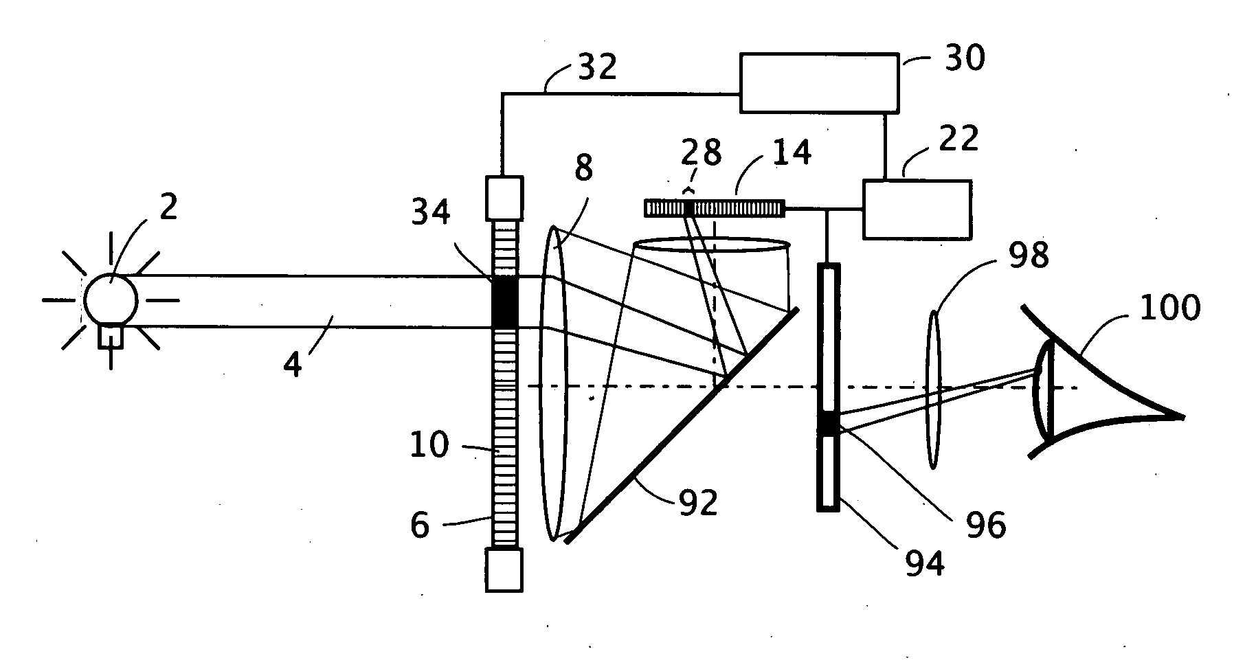
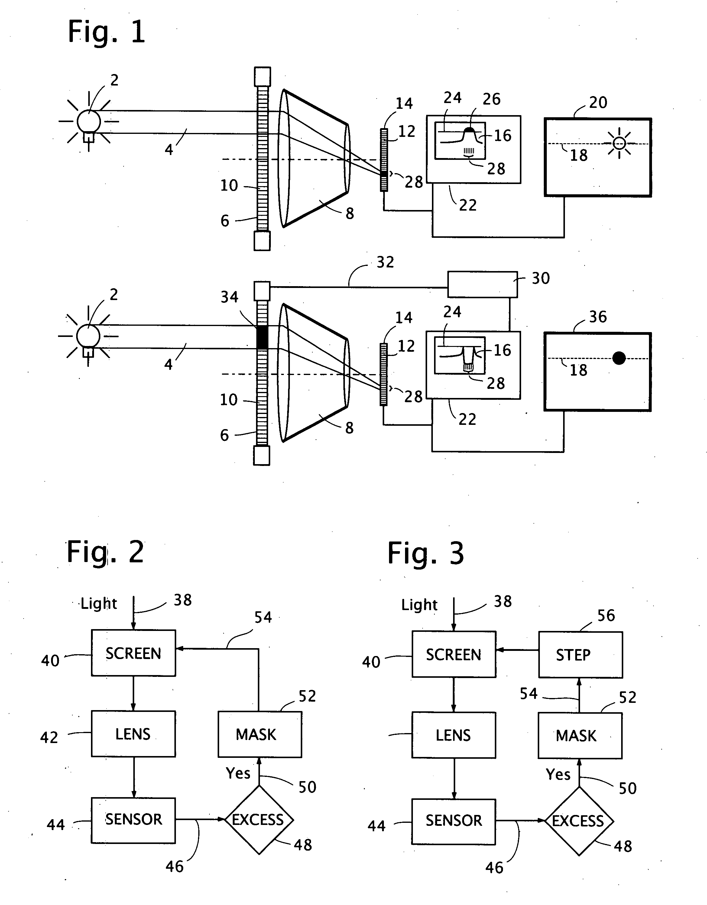
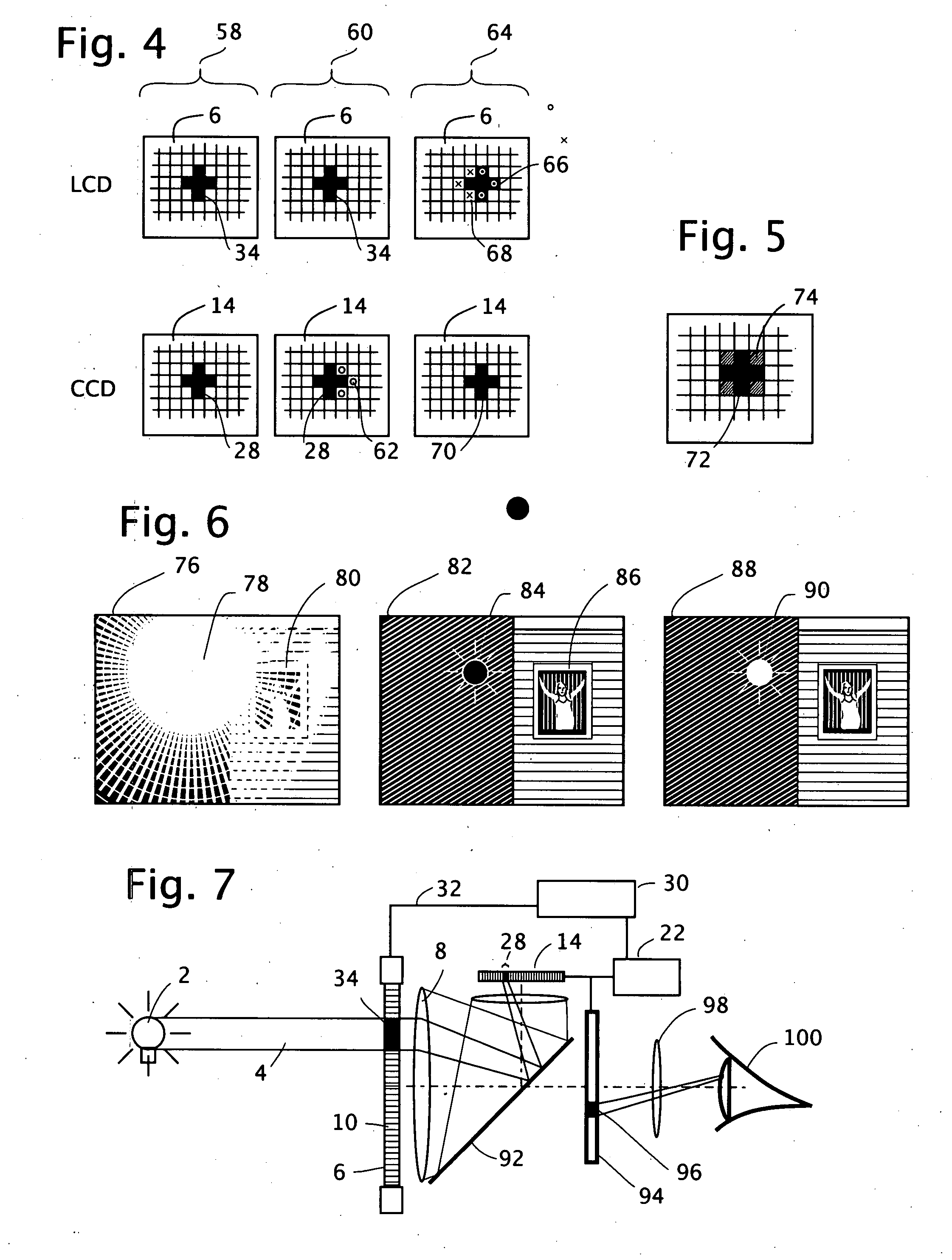
[0022]In the present invention, in an electronic imaging system, which can be either analog or digital, a variably transmissive pixellated screen such as a clear liquid crystal display (LCD) screen is placed in front of the camera lens and an image sensor is in back of the lens and in line with its optical axis, so that the image sensor is exposed to light representing the components of a field of view. There are several methods of construction used to make an LCD screen. In one implementation, the construction of an LCD includes two oppositely oriented polarizing filters with polarizations orthogonal to each other. Between them, contained within clear substra...


PUM


Abstract

An active pixel masking system for automatic glare suppression uses a variably transmissive screen such as an LCD in front of a lens. A measurement by an image sensor of oversaturated pixels from one or more extremely bright lights is used to generate corresponding opaque pixels in the variably transmissive screen, thereby preventing the excess light from entering the lens, and thereby clarifying the appearance of any objects near to the bright light. A continuous reading of a motion picture image is used to move the location and area of the opaque pixels in response to the motion and area of the light.

Description

RELATED APPLCIATION[0001]This application claims priority from U.S. provisional application No. 60 / 819,187 filed Jul. 7, 2006.FIELD OF THE INVENTION[0002]This invention generally relates to optical devices for lenses. It also is related to digital video and other electronic image camera systems.BACKGROUND ART[0003]The experience of photography outdoors typically has to contend with the sun. The bright, concentrated light from the sun, especially on a cloudless day, causes glare as it enters a camera lens, and washes out detail nearby to the sun in the camera image. In some cases, this means that a significant amount of the potential image is lost. The same phenomenon can be found with other bright light sources such as headlights and streetlamps in a night scene.[0004]Bright lights cause many adverse effects in an electronic imaging system. In analog imaging systems such as vidicon tubes, the burned-in area from such a bright light source can causes a trail to be left behind when ei...

Claims


Application Information

Patent Timeline
Patent Type & Authority Applications(United States)
IPC IPC(8): H04N5/225
CPCH04N5/238H04N23/75
Inventor MCCUTCHEN, DAVID
Owner IMMERSIVE LICENSING
Why Eureka
Try Eureka