Image-forming apparatus to form an image based on print data, print-job control method, and print-job control program embodied in computer readable medium

Active Publication Date: 2008-01-10
KONICA MINOLTA BUSINESS TECH INC
View PDF6 Cites 60 Cited by
  • Summary
  • Abstract
  • Description
  • Claims
  • Application Information

AI Technical Summary

Benefits of technology

[0007]It is an object of the present invention to solve the above problems. It is another object of the present invention to provi

Problems solved by technology

Conversely, if the predetermined range is set to be small in order to prevent mal-op

Method used


Image

  • Image-forming apparatus to form an image based on print data, print-job control method, and print-job control program embodied in computer readable medium
  • Image-forming apparatus to form an image based on print data, print-job control method, and print-job control program embodied in computer readable medium
  • Image-forming apparatus to form an image based on print data, print-job control method, and print-job control program embodied in computer readable medium

Examples


first modified example

[0112]In the above embodiment, the MFP 100 starts a preparation operation to form an image upon approach to the MFP 100 within the first distance by a user who carries the mobile communication terminal 250, and starts image formation upon reduction of the distance below the second distance. In a first modified example, the image-forming operation is executed in a stepwise manner according to the distance between the MFP 100 and the user. FIG. 15 is a diagram illustrating a first range, a second range, and a third range that are based on the MFP 100. Referring to FIG. 15, a first range 301 is between the MFP 100 and the first range, and above a third distance. The third distance is shorter than the first distance and longer than a second distance. A third range 303 is between the MFP 100 and the third distance, and above the second distance. A second range 302 is between the MFP 100 and the second distance.

[0113]The MFP 100 in the modified example starts a first preparation operation...

second modified example

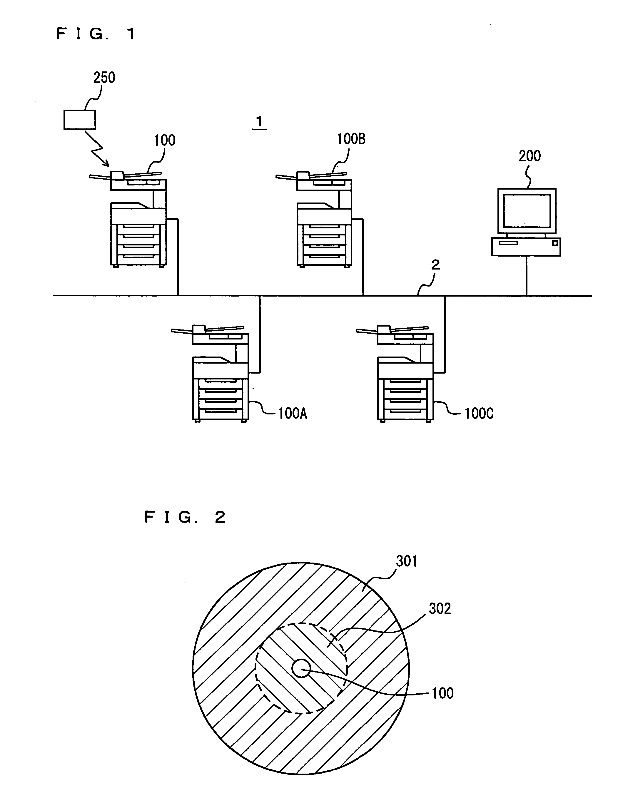
[0119]FIG. 19 is a schematic diagram of an image-forming system 1A according to a second modified example. Referring to FIG. 19, a radio base station 401 is connected to the network 2 in addition to the PC 200 and the MFPs 100, 100A, 100B, and 100C. In the second modified example, the PC 200 and the MFPs 100 and 100A are provided in a first area, which is a business establishment A here, and the MFPs 100B and 100C and the radio base station 401 are provided in a second area, which is a business establishment B here. The radio base station 401 is located at a reception where a user passes when entering the site of the business establishment B. The radio base station 401 has similar functions to those of the radio communication portion 108 provided in the MFPs 100, 100A, 100B, and 100C, and in addition, has a communication interface through which to connect to the network 2. Here the radio base station 401 is set to be communicable with the MFPs 100B and 100C.

[0120]Assume that a user ...


PUM


Abstract

In order to shorten the waiting time and to prevent confidential data from being seen by others, an MFP has a distance measuring portion to communicate with a radio communication terminal and measure a distance between the MFP and the radio communication terminal, a print-job acquiring portion to acquire print data, an image-forming portion to form an image, and an image forming control portion to start a preparation operation to cause the image-forming portion to form an image, upon reduction of the measured distance equal to or below a first threshold value, and to cause the image-forming portion to form an image based on the acquired print data, upon reduction of the measured distance equal to or below a second threshold value smaller than the first threshold value.

Description

READABLE MEDIUM[0001]This application is based on Japanese Patent Application No. 2006-188860 filed with Japan Patent Office on Jul. 10, 2006, the entire content of which is hereby incorporated by reference.BACKGROUND OF THE INVENTION[0002]1. Field of the Invention[0003]The present invention relates to an image-forming apparatus to form an image based on print data, a print-job control method executed in the image-forming apparatus, and a print-job control program embodied in a computer readable medium and executed in the image-forming apparatus.[0004]2. Description of the Related Art[0005]In recent years, it has become common to connect image-forming apparatuses such as printers to networks. In this form of use, image-forming apparatuses are used in common by a plurality of users. Here, when a user instructs a computer connected to a network to transmit print data to an image-forming apparatus, and when the image-forming apparatus is located at some distance from the computer, it c...

Claims


Application Information

Patent Timeline
IPC IPC(8): G06F3/12
CPCG06F21/35G06F21/608G06F2221/2117H04N1/00931H04N2201/0094H04N1/0097H04N1/00973H04N1/32117H04N1/32502H04N1/00933
Inventor ISHIMARU, KOHJI
Owner KONICA MINOLTA BUSINESS TECH INC
Why Eureka
Try Eureka