Active balancing circuit modules, systems and capacitor devices

a technology of active balancing circuit and capacitor, which is applied in the association of fixed capacitor details, printed circuit non-printed electric components, instruments, etc., can solve the problems of capacitor failure, subsequent gas generation, and excessive leakage curren

Active Publication Date: 2008-01-10
EATON INTELLIGENT POWER LIMITED
View PDF11 Cites 20 Cited by
  • Summary
  • Abstract
  • Description
  • Claims
  • Application Information

AI Technical Summary

Problems solved by technology

A capacitor is often designed with a maximum operating voltage rating where operation above this maximum operating voltage rating will generally lead to excessive leakage current, subsequent gas generation, and ultimately failure of the capacitor.
Although passive balancing may work initially, passive balanc

Method used


Image

  • Active balancing circuit modules, systems and capacitor devices
  • Active balancing circuit modules, systems and capacitor devices
  • Active balancing circuit modules, systems and capacitor devices

Examples


example

[0063] To further understand the benefits of the present invention, the following example provides details concerning an active balancing system with active balancing modules in accordance with one embodiment of the present invention. It should be understood the following is representative only, and that the invention is not limited by the detail set forth in this example.

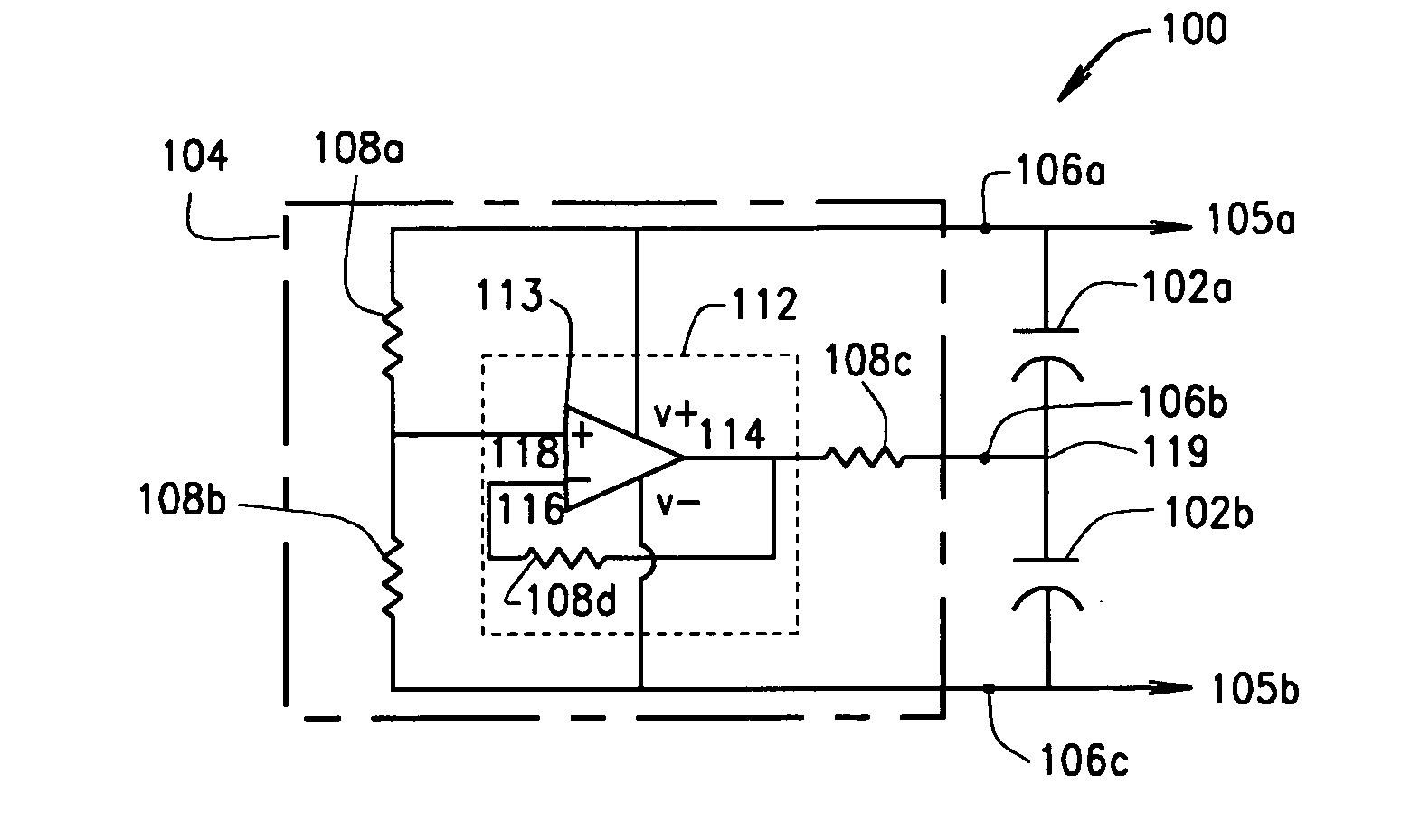
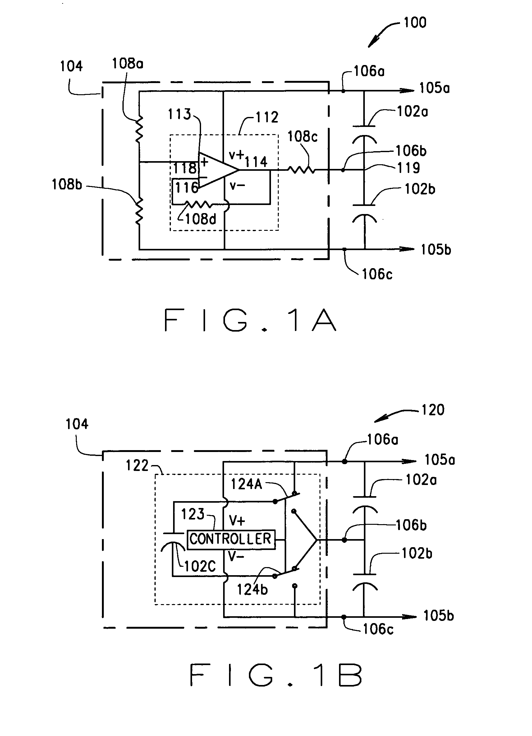
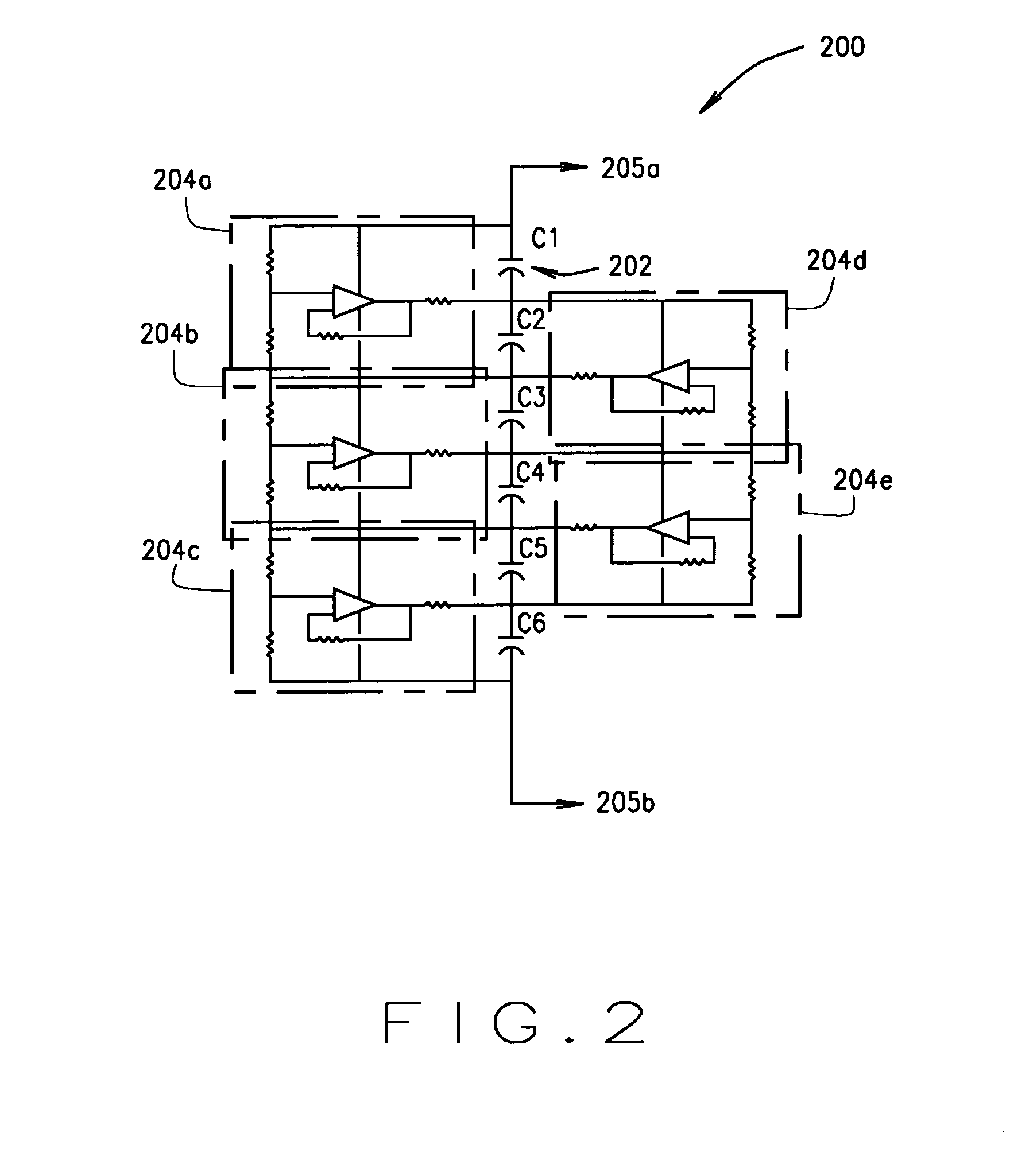
[0064]FIG. 3 illustrates an active balancing system 300 that includes a plurality of capacitors 302 (e.g., 302a, 302b, 302d) coupled to multiple active balancing modules 304 (e.g., 304a, 304b). FIG. 3 illustrates the concept introduced by system 120 and system 200. As shown, active balancing modules 304a and 304b implement flying capacitor devices. With respect to active balancing module 304a, the flying capacitor device includes a switched voltage converter 326a in connection with a flying capacitor 302c. On the other hand, the flying capacitor device for active balancing module 304b includes a switched voltage c...


PUM


Abstract

Circuit modules, systems and devices for controlling voltages across capacitors.

Description

CROSS REFERENCE TO RELATED APPLICATIONS [0001] This application is a continuation-in-part application of U.S. application Ser. No. 10 / 781,571 filed Feb. 17, 2004 and entitled Active Balancing Modular Circuits, the disclosure of which is hereby incorporated by reference in its entirety.BACKGROUND OF THE INVENTION [0002] This invention relates generally to The present invention relates to active balancing circuitry for capacitors and methods for their manufacture. More particularly, the invention relates to a module based active balancing circuitry for capacitors stacked in a series arrangement. [0003] A capacitor is often designed with a maximum operating voltage rating where operation above this maximum operating voltage rating will generally lead to excessive leakage current, subsequent gas generation, and ultimately failure of the capacitor. In order to construct capacitances for higher voltage applications, capacitors of identical value and rating are stacked in a series arrangem...

Claims


Application Information

Patent Timeline
IPC IPC(8): H01G9/00
CPCH01G4/255H01G4/40H02M2001/009H02J7/0016H01G9/14H02M1/009H02J7/345H02M3/07H02M3/18
Inventor DOLJACK, FRANK
Owner EATON INTELLIGENT POWER LIMITED
Why Eureka
Try Eureka