Crown for Timepiece With Disconnecting Gear Device

a technology of gear device and crown, which is applied in the direction of normal winding, horological winding mechanism, instruments, etc., can solve the problems of difficult mounting of various springs in the crown, complex structure disclosed and shown, and difficulty in manufacturing and assembly of various springs

Active Publication Date: 2008-01-10
MECO SA
View PDF9 Cites 9 Cited by
  • Summary
  • Abstract
  • Description
  • Claims
  • Application Information

AI Technical Summary

Benefits of technology

[0014] Preferably, the deformable element and the rigid element are respectively made of metals whose respective hardnesses are close, this feature guaranteeing proper longevity for the device according to the present invention.

Problems solved by technology

In fact, the structure disclosed and shown is complex both from the manufacturing and assembly point of view, in particular because of the dimensions to be considered within the field of crowns for horology.
Manufacturing the various springs implemented is difficult, on the one hand because of their shape, and on the other hand, because they are mounted pre-stressed, which makes it difficult to mount them in the crown.
Another drawback of the device disclosed in U.S. Pat. No. 2,637,987 arises from the necessity of providing a particular shape for the end of the winding stem arranged inside the crown, such that it can cooperate with the particular shape used for the spring.
This constraint forces the manufacturer to provide different manufacturing processes for the different winding stem shapes to be used, thereby causing extra costs.

Method used


Image

  • Crown for Timepiece With Disconnecting Gear Device
  • Crown for Timepiece With Disconnecting Gear Device
  • Crown for Timepiece With Disconnecting Gear Device

Examples


Embodiment Construction

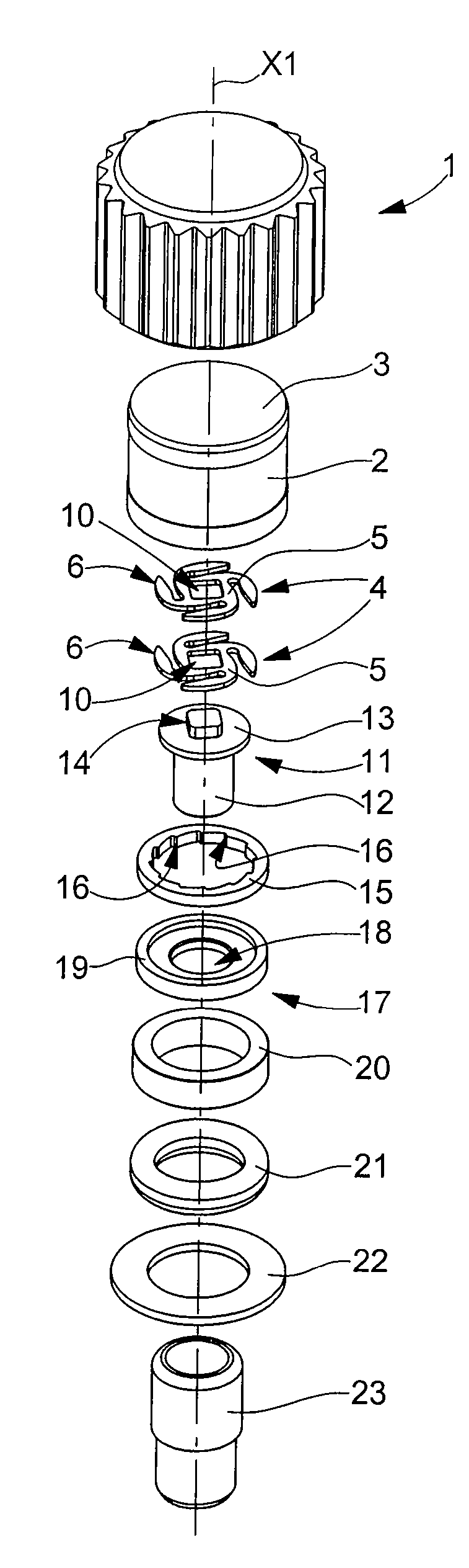
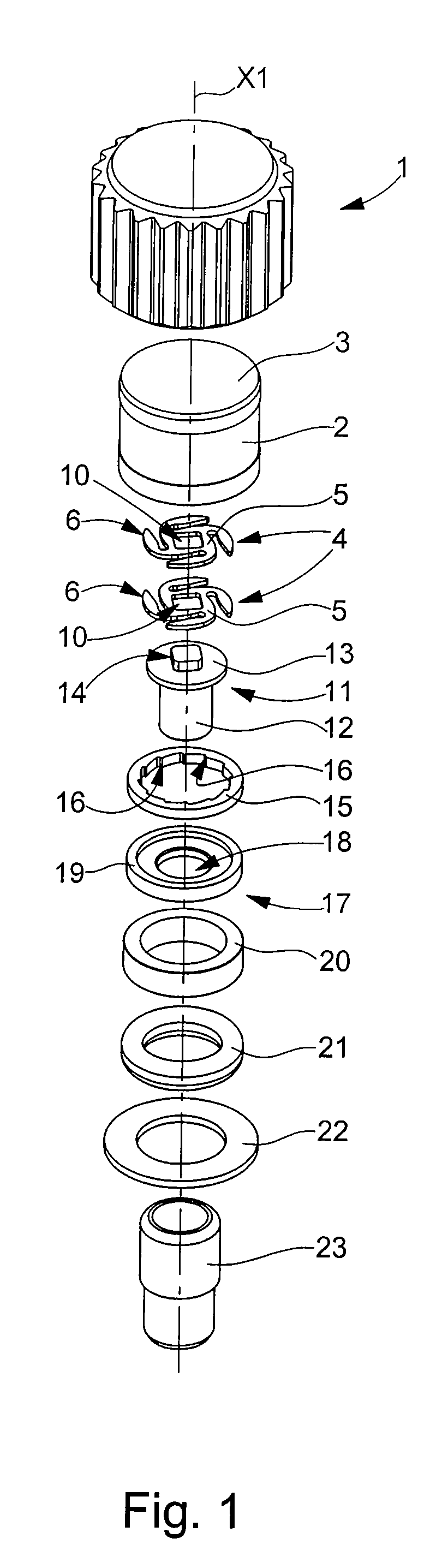
[0019]FIG. 1 shows an exploded perspective view of the crown according to a preferred embodiment of the present invention demonstrating the simplicity of the corresponding structure and the simplicity of assembly of the various components with each other.

[0020] The various constituent elements of the crown according to the invention are shown in an order schematising the assembly sequences thereof in FIG. 1.

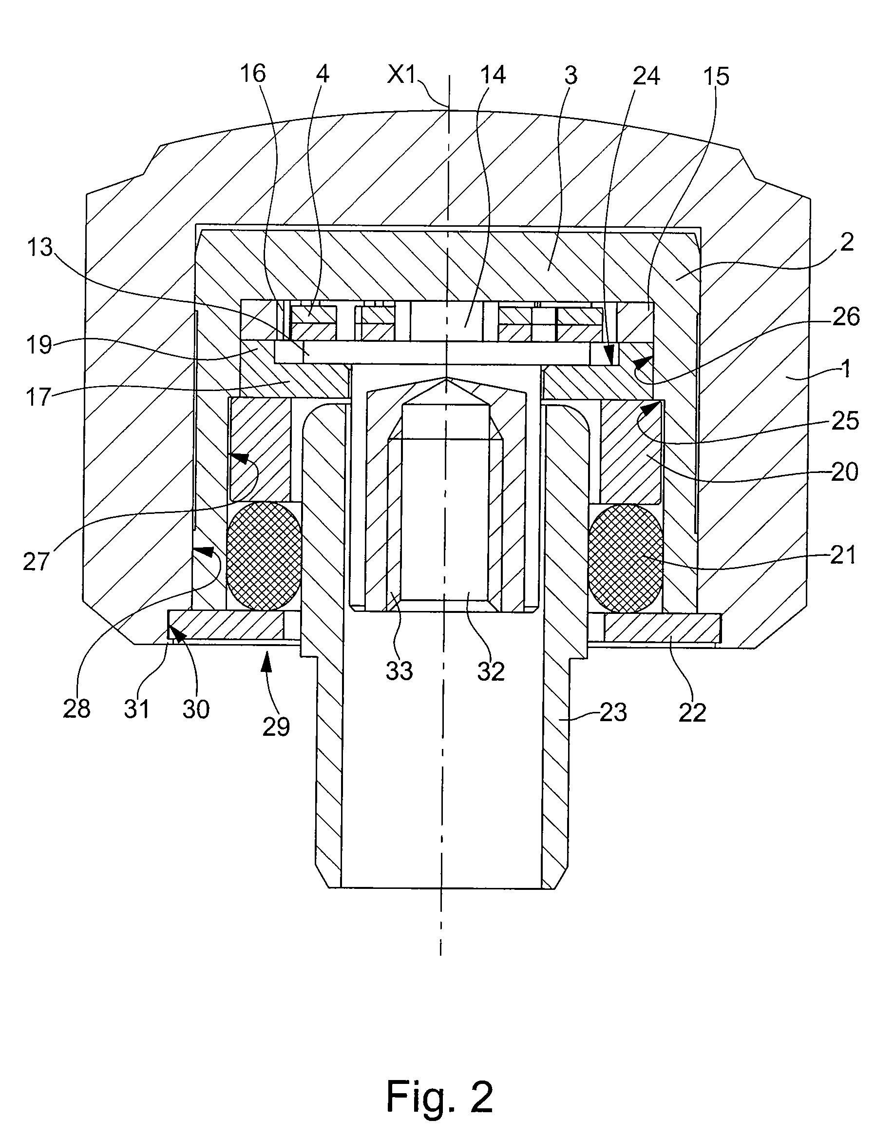
[0021] The numerical reference 1 designates the crown itself, the latter having rotational symmetry of axis X1 and being hollow so as to define a housing (visible in FIG. 2) for housing the following components. A hollow support element 2 whose dimensions are adjusted to the dimensions of the crown housing has the shape of a cylinder, closed on one side by way of illustration, by a bottom 3. There are then two identical springs 4 to be arranged in proximity to the bottom 3 of support element 2. Two identical springs 4 are provided here because of the thickness of the material n...


PUM


Abstract

The present invention concerns a crown for a timepiece comprising a disconnecting gear device for preventing damage to the components of the movement of the timepiece in which it is implemented. For this purpose, the crown is provided with a housing which houses a pipe, to which one end of a winding stem is connected, carrying at least one spring and a rigid ring secured to the crown and comprising notches adapted to cooperate with the spring. In common use, a rotation of the crown causes a rotation of the pipe and thus of the winding stem, via the rigid ring and the spring. Owing to the device according to the present invention, when the mechanical resistance to the rotation opposed by the winding stem, via the pipe, exceeds a predefined threshold, the spring is deformed and is no longer driven in rotation by the rigid ring. Consequently, the winding stem is no longer driven in rotation in such conditions.

Description

FIELD OF THE INVENTION [0001] The present invention concerns a crown for a timepiece comprising a housing of axis X1 inside which is arranged a pipe including, in the region of a first end, means for securing a winding stem. The housing also includes at least a first element, able to be deformed in a resilient manner, cooperating via friction in a movement of rotation in relation to axis X1, at least in a first direction of rotation, with one rigid element of suitable shape, as long as the rotational couple transmitted by one of these elements to the other remains lower than a predefined value. Beyond the predefined value, the first deformable element is capable of being deformed to cause a sliding connection between said element and the rigid element. BACKGROUND OF THE INVENTION [0002] These types of crowns comprising a disconnecting gear device are known in the prior art. Such devices are known to be implemented, for example, to prevent damaging the mechanism of a timepiece when t...

Claims


Application Information

Patent Timeline
Patent Type & Authority Applications(United States)
IPC IPC(8): G04B3/04G04B29/00G04B3/06
CPCG04B3/06
Inventor ZIMMERMANN, GEORGES
Owner MECO SA
Why Eureka
Try Eureka