Systems and Methods for Implanting Tissue Stimulation Electrodes in the Pelvic Region

a tissue stimulation electrode and pelvic region technology, applied in the field of implantable medical devices, can solve the problems of inability to tolerate chronic stimulation, and inability to tolerate pelvic muscles,

Inactive Publication Date: 2008-01-10
BOSTON SCI SCIMED INC
View PDF99 Cites 62 Cited by
  • Summary
  • Abstract
  • Description
  • Claims
  • Application Information

AI Technical Summary

Problems solved by technology

As set forth in U.S. Pat. No. 6,964,699, urinary incontinence is a significant clinical problem and a major source of disability and dependency.
As set forth in U.S. Pat. No. 6,896,651, male or female stress urinary incontinence (SUI) occurs and results from weakness or inability of pelvic muscles to hold back urinary flow from the bladder when abdominal pressure increases due to common physical or emotional stress events, such as coughing, laughing or mild physical exertion.
Frequency or urgency involves the need or urge to urinate on an excessively frequent or habitual basis.
Although such stimulation has shown therapeutic effects, electrode placement and on-going stimulation do not lend themselves easily to chronic stimulation.
This method of positioning the stimulation electrodes in or proximate the urethral sphincter surrounding the urethra can be troublesome since there is a tendency that the stimulation electrode will be retracted when the introducer sleeve is split and withdrawn.
In addition, the routing of the lead body through the subcutaneous pathway relative to the pubic bone can also stress the lead body and contribute to electrode dislodgement.
A suture sleeve may be employed, but it may be difficult to locate the relatively bulky sleeve in a place where suturing to tissue would be effective.
Active fixation helical screws and hooks are not suitable for fixation to or about nerves due to the potential for nerve damage during implantation or due to micro-dislodgement in chronic implantation.
Unlike the myocardium of the heart, the tissue structure adjacent the urethra or anus is relatively soft, and hook or spiral active fixation devices do not hold as well as they do in the myocardium.

Method used


Image

  • Systems and Methods for Implanting Tissue Stimulation Electrodes in the Pelvic Region
  • Systems and Methods for Implanting Tissue Stimulation Electrodes in the Pelvic Region
  • Systems and Methods for Implanting Tissue Stimulation Electrodes in the Pelvic Region

Examples


Embodiment Construction

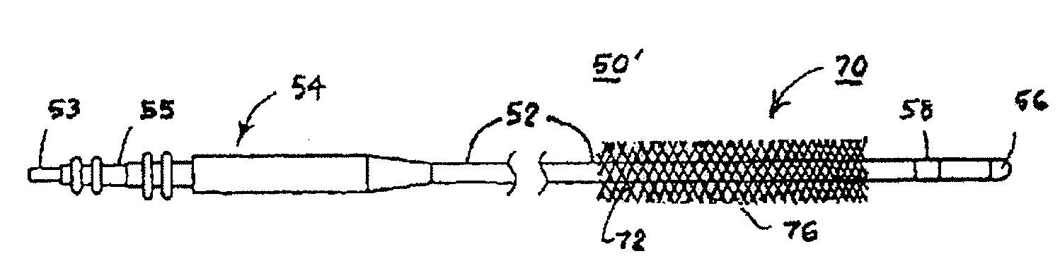
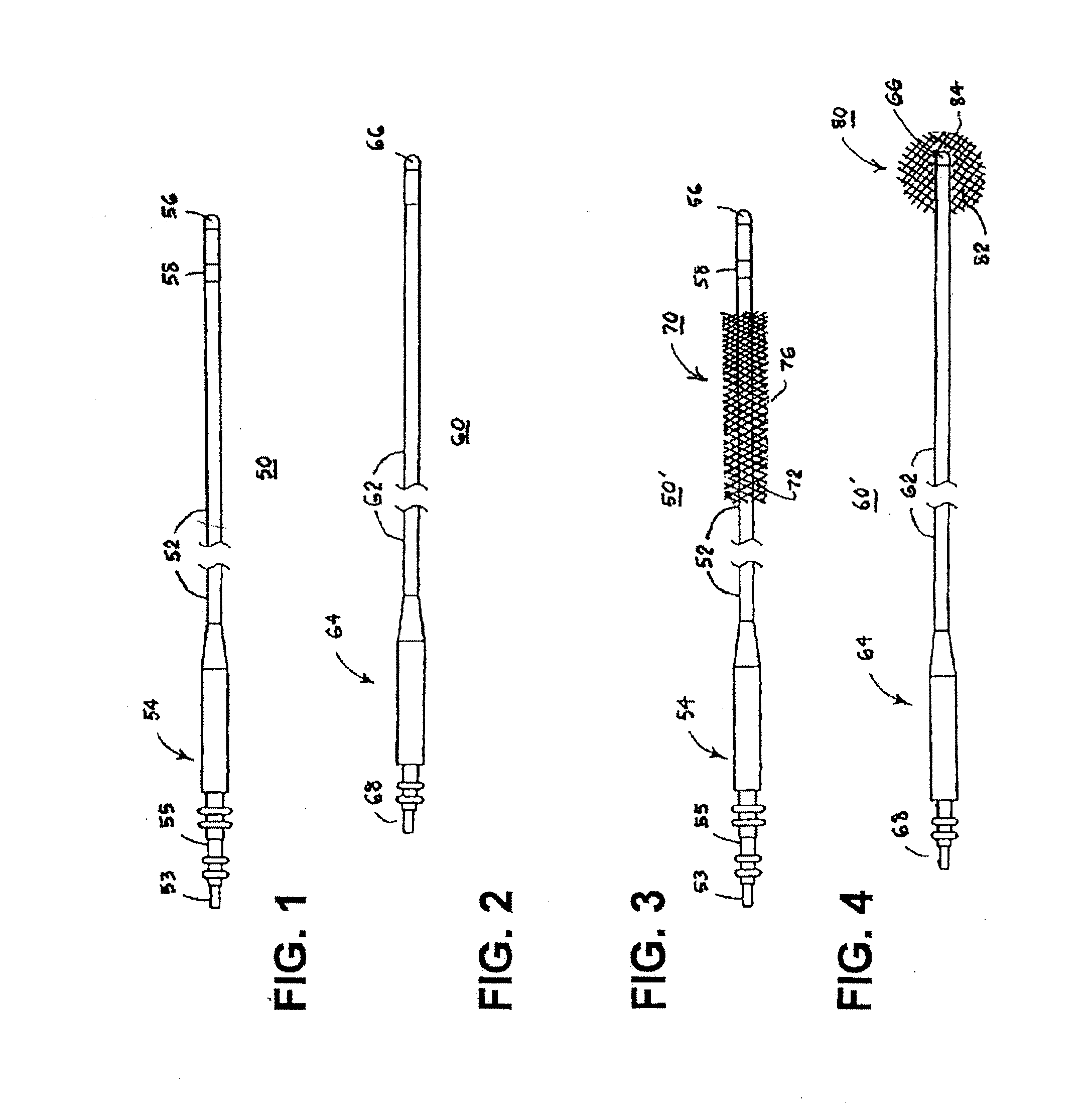
[0068]For convenience, the expressions “tissue stimulator” and “tissue stimulation” are employed herein to characterize implantable stimulators comprising electrical medical leads and IPGs and the stimulation applied to tissue structures of the abdominopelvic or simply pelvic region to enervate to cause muscle tissues to contract.

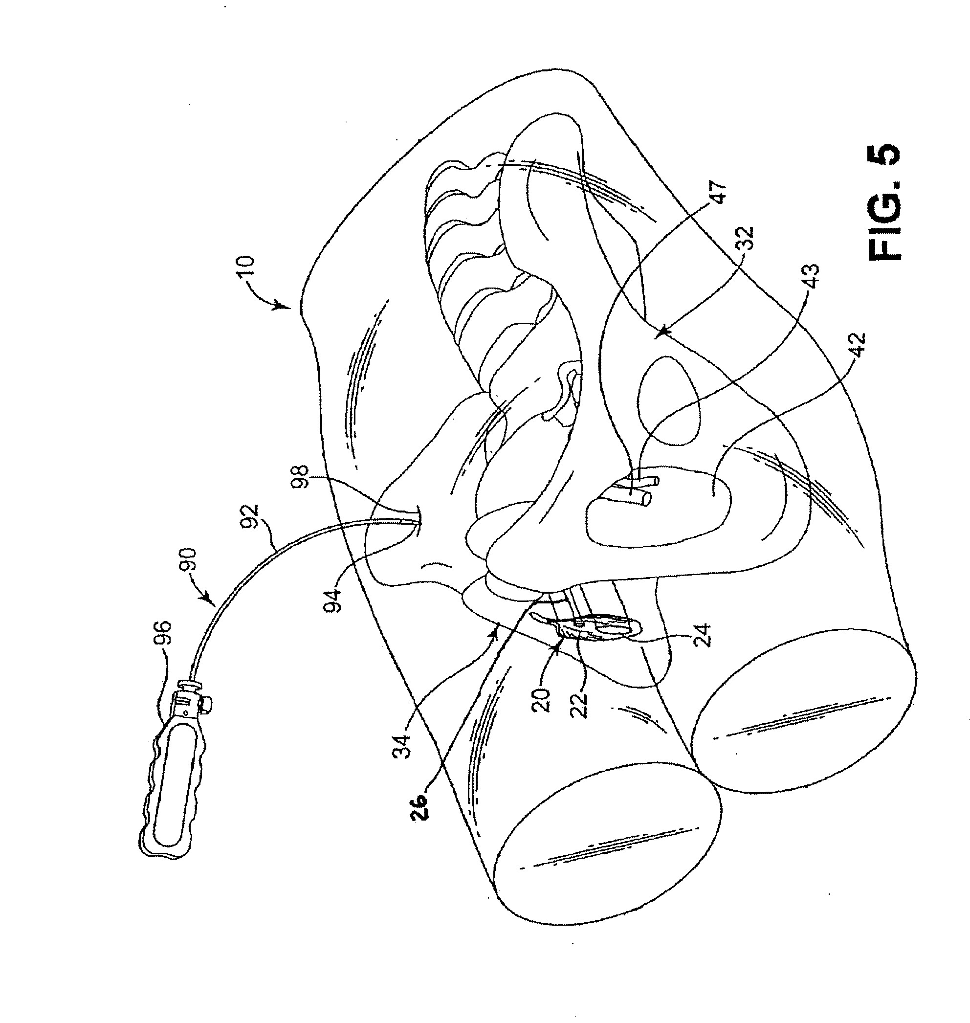
[0069]Various features and aspects of the present invention may be practiced separately or in combination and may find application in the positioning and fixation of tissue stimulation leads in various parts of the pelvic region to treat various pelvic disorders. The illustrated embodiments depict tissue stimulation electrode positioning and stabilization in urethral tissue structure of a female patient for alleviating urethral incontinence, but the same or similar procedures and / or devices may be employed in electrode positioning and stabilization in urethral tissue structures of a male patient for alleviating urethral incontinence. Moreover, in either mal...


PUM


Abstract

Implantable medical devices to relieve problems associated with incontinence and related pelvic disorders and methods of implanting same are disclosed. Stimulation leads for placement in the pelvic floor have fixation mechanisms for stabilization of the stimulation electrodes to inhibit dislodgement from a selected stimulation site. In certain embodiments, the fixation mechanisms encourage fibrosis about the lead to chronically stabilize the position of the stimulation lead and / or stimulation electrode(s). In certain embodiments, the fixation mechanisms are isolated from body tissue during routing of the stimulation lead through a tissue pathway and then exposed to body tissue to encourage fibrosis.

Description

CROSS-REFERENCE TO RELATED APPLICATIONS[0001]This application claims priority under 35 USC §119(e) to U.S. Provisional Application Ser. No. 60 / 806,799 filed Jul. 10, 2006, the entire contents of which is incorporated herein by reference.[0002]Reference is hereby made to commonly assigned, copending U.S. patent application Ser. No. 11 / 418,790, filed May 5, 2006, entitled “Apparatus for Treating Stress & Urge Incontinence” and incorporated herein by reference.[0003]Reference is hereby made to commonly assigned, copending PCT Application No. PCT / US2007 / 004474 filed Feb. 22, 2007, entitled “Electrode Sling for Treating Stress and Urge Incontinence” and incorporated herein by reference.TECHNICAL FIELD[0004]The present invention relates generally to implantable medical devices, and specifically to implantable medical devices to relieve problems associated with incontinence and related pelvic disorders.BACKGROUND[0005]Implantable medical devices (IMDs) that generate and apply to excitable ...

Claims


Application Information

Patent Timeline
Patent Type & Authority Applications(United States)
IPC IPC(8): A61N1/05
CPCA61N1/0558A61N1/05
Inventor BUYSMAN, JOHN JASONLUND, ROBERT E.MUJWID, JAMES R.GOHMAN, JAMES A.
Owner BOSTON SCI SCIMED INC
Why Eureka
Try Eureka