
Disk device

a technology of a disk drive and a drive body, which is applied in the direction of recording information storage, instruments, etc., can solve the problems of serious problems such as the inability to automatically eject the disk, the state of unwanted presence of the disk in the optical disk drive, etc., and achieve the effect of reducing the load, facilitating the push of the external device, and ensuring safe unloading and removing the disk

Inactive Publication Date: 2008-01-10
TEAC CORP
View PDF9 Cites 16 Cited by
  • Summary
  • Abstract
  • Description
  • Claims
  • Application Information

AI Technical Summary

Benefits of technology

[0010]In view of the foregoing problems, an object of the present invention is to provide a disk device for driving a disk, the disk device having a mechanism for disk ejection in a forcible manner, and being manually operable with great ease by reduction of load required for forcible ejection of the disk.
[0012]The specific disk ejector shifts the first gear wheel to the disengaged position in an initial step of the push of the external device, and then causes the second gear wheel to rotate at a predetermined amount. The specific disk ejector actuates the disk transport mechanism intermittently by the push of the external device at plural times, to move back the disk to the ejection position. Furthermore, a biasing member moves the specific disk ejector to an initial position when the push of the external device discontinues. The specific disk ejector further prevents the second gear wheel from rotating in a second direction reverse to the first direction in moving back to the initial position. Prevention of the second gear wheel from rotating in the second direction is substantially simultaneous with shift of the first gear wheel to the disengaged position.
[0016]Each of teeth of the rack gear includes a first tooth surface, being erect, for rotating the second gear wheel in the first direction when the driving structure moves from the second position to the third position. A second tooth surface is tilted, for facilitating passage of a tooth tip of the second gear wheel when the driving structure moves back from the third position to the second position.
[0020]Accordingly, it is possible to reduce load required for forcible ejection of a disk because the gear in the transmission gear mechanism is disengaged for the purpose of emergency ejection of the disk upon push of an external device or emergency pin. Operation for the push of the external device is facilitated. There is no mechanical stress because of the state free from forcibly rotating the transmission gear mechanism. Furthermore, it is possible in the type of repeated push of the external device or emergency pin for the ejection to eject a disk in a completed stopped state even upon the push during a high speed rotation of the disk. Thus, it is possible to unload and withdraw the disk safely.

Problems solved by technology

Should failure occur according to disconnection of a power source or mechanical failure of the optical disk drive itself, no automatic ejection of the disk can be made.
The state of unwanted presence of the disk in the optical disk drive is a serious problem.

Method used


Image

  • Disk device
  • Disk device
  • Disk device

Examples


Embodiment Construction

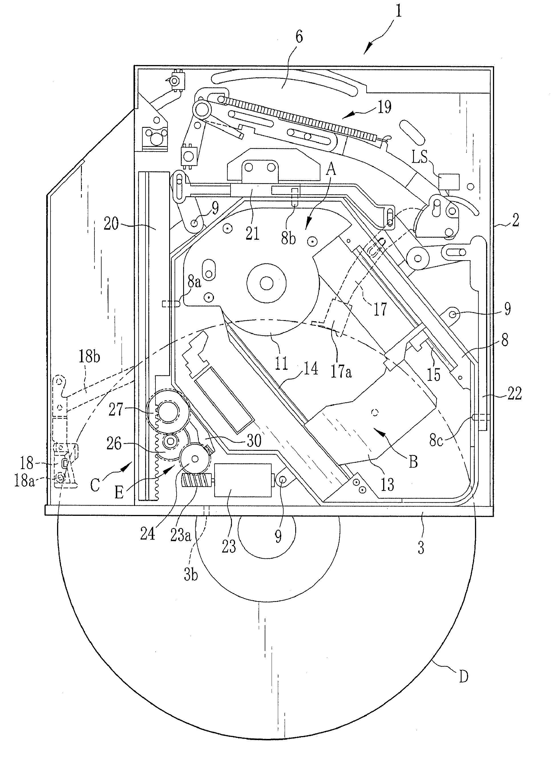
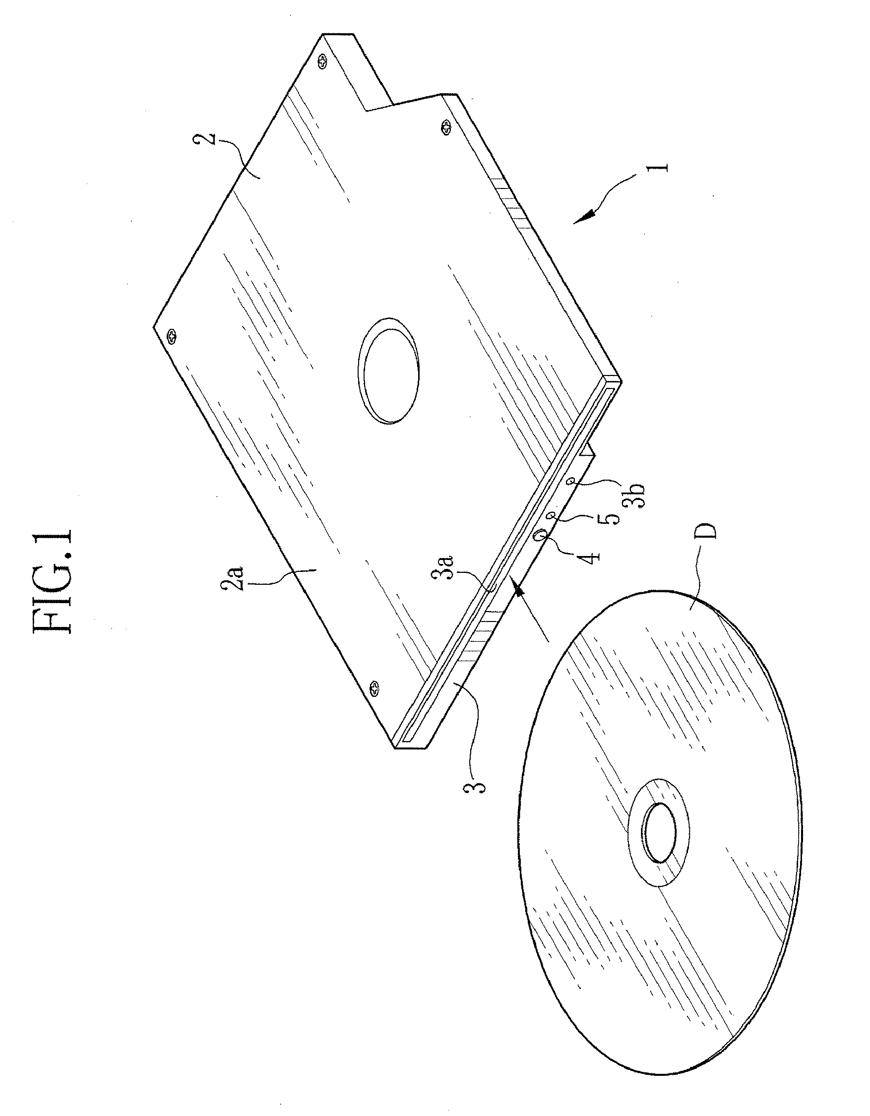
[0035]In FIG. 1, an optical disk drive 1 or player as optical disk device has a case chassis 2 constructed in a shielded state. A front bezel 3 is fitted on the case chassis 2. An insertion slot 3a is formed in the front bezel 3 for insertion of an optical disk D. An emergency hole 3b is formed in the front bezel 3 for emergency ejection of the disk D in a forcible manner. An ejection button 4 and a loading indicator 5 are disposed on the front bezel 3. The ejection button 4 is depressed for ejection of the optical disk D. The loading indicator 5 illuminates to indicate a status of operation of the optical disk drive 1. An upper panel 2a of the case chassis 2 is constructed removably.

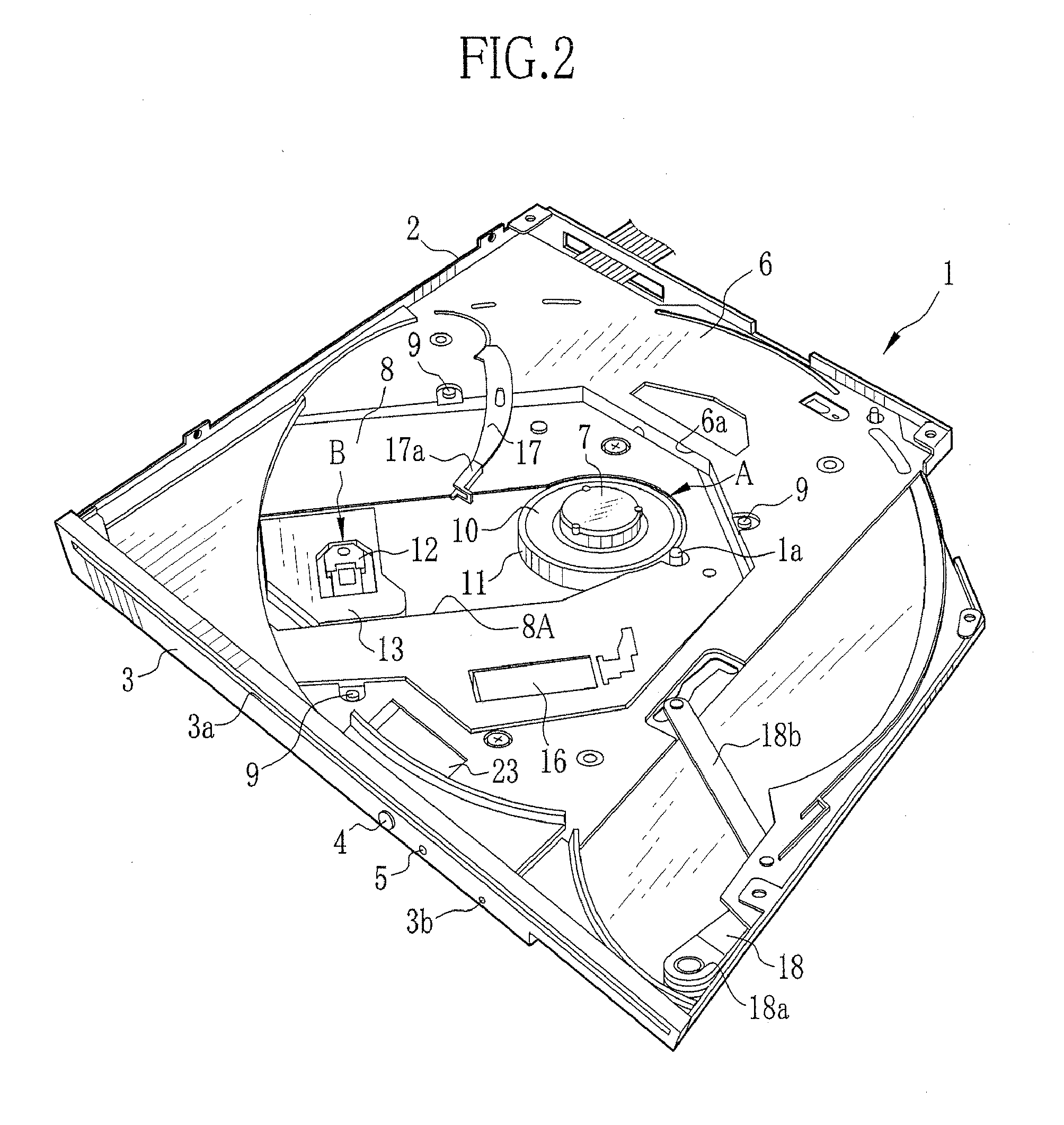
[0036]In FIGS. 2 and 3, a base panel 6 is fixedly secured to the case chassis 2 to split the inside of the case chassis 2 in upper and lower regions. An opening 6a is formed in the base panel 6, and extends from the center diagonally. A lifting frame 8 is disposed in the opening 6a. A cushioning support...


PUM

PropertyMeasurementUnit
forceaaaaaaaaaa
resiliencyaaaaaaaaaa
resilient deformationaaaaaaaaaa

Abstract

A disk transport mechanism in a disk drive is connected with a transmission gear mechanism. A loading motor drives the disk transport mechanism. When the loading motor rotates forwards, an optical disk is carried by the disk transport mechanism to a chuck position. When the loading motor rotates backwards, the optical disk is moved back to an ejection position. In failure of the loading motor, an emergency pin is pushed to actuate an emergency disk ejector. A first gear wheel in the transmission gear mechanism is disengaged by the emergency disk ejector to separate the transmission gear mechanism into a disk transport mechanism side and a motor. A second gear wheel on the disk transport mechanism side is rotated to actuate the disk transport mechanism. The emergency pin is pushed repeatedly to cause the disk transport mechanism to move back the optical disk to the ejection position.

Description

BACKGROUND OF THE INVENTION[0001]1. Field of the Invention[0002]The present invention relates to a disk device for driving a disk. More particularly, the present invention relates to a disk device for driving a disk, the disk device having a mechanism for disk ejection in a forcible manner.[0003]2. Description Related to the Prior Art[0004]An optical disk is an information recording medium for use in a computer system or other electronic equipment for storing information of a considerable amount, for example, CD-R / RW, DVD-R / −RW / RAM / +R / +RW. An optical disk drive or player as optical disk device is loaded with the optical disk, and accesses the optical disk to write information to or read information from the optical disk. One of two well-known types of the optical disk drives is a tray type. The tray type includes a disk tray, which is movable between a contained position and an ejection position, and when in the contained position, is contained in a case chassis, and when in the eje...

Claims


Application Information

Patent Timeline
Patent Type & Authority Applications(United States)
IPC IPC(8): G11B17/04
CPCG11B17/051G11B17/04
Inventor FUJISAWA, SHINICHI
Owner TEAC CORP
Learn More