4D simultaneous robotic containment with recoil

a robotic containment and recoil technology, applied in the direction of shields, reactive armour, offensive equipment, etc., can solve the problems of many solar powered vehicles, insufficiently addressing mines, and putting an equivalent number of humans at risk, and achieves cost-effectiveness, small size, and durable and cost-sacrificial

Inactive Publication Date: 2014-03-25
DIAZ KEVIN MARK
View PDF57 Cites 12 Cited by
  • Summary
  • Abstract
  • Description
  • Claims
  • Application Information

AI Technical Summary

Benefits of technology

[0009]It is the objective of the present invention to create a new use for a solar powered vehicle to provide a improved combined compact mine detector, monitor and sweeper and containment apparatus in the most austere environments to run without conventional fuel driven power using only Green Technology. The vehicle is a battery based DC (direct current) motor drive recharged with a solar module attached onto the forward sloping frame. It does not require daily fueling. Introducing equipment that is designed to be small in size and intended to be durable and cost sacrificial utilizing mechanical and detection means having the advantage of self-contained capabilities. The goals and approach are solely based on control of spaces at risk to mine placement and provide a cost-effective, high performance solution with known survivability limitations and budget-sacrificial equipment loss and only life saving and casualties reduction made as a variables of measured value.
[0014]The various elements that work together or individually in turn function together in an accumulating efficient manner reducing battery load requirements to operate the vehicle mechanical functions and computer systems. The components and assemblies are described as a prestage gas ejection detector, probe head boot, a strut probe assembly to impart a minimum of downward force, a timed pressure manifold for strut(s) and a strut energy dissipating canopy with chute.
[0015]As the prevention of mine accidents is paramount, longer operating times for the mine defeat system are preferred increasing daily service time. Each element described contributes to lowering energy demand and / or vehicle stability.
[0017]The pressure manifold and relay is located in an area away from the containment space. It combines the signaling of the probe head cycle for probe extension with the opening and closing of volume space in the strut(s). The function of controlled volume is provided with the primary feature of strut rod movement. Additional mine detectors will enhance the triggering to dissipation process.
[0018]The ability of the machine's probing units to move along will be improved by utilizing carbon fiber or other blast resistant material wrapped around the base of the probe or shoe acting as a flexible boot. A positioning of a mine detector will allow for prestage gas ejection. The probe head assembly may utilize a control ball knuckle for limited directional range of motion.
[0019]The placement prevention of mines is simultaneously done in a passive format through constant motion and personnel verification using a 360-degree turret to create safe-zones, which is a primary focus for all countries. In each typical village, small areas shall benefit, primarily villages and village connecting trails. Rotation of the camera of 45 degrees to left and right provides 360 degree of coverage with the turret operational. The majority of mines are delivered and set in place by individuals or groups who reside outside the community or village at risk. As an advantage in the self-contained and efficient capabilities, the vehicle is able to continuously perform motion detection and identification checking, through this simple but new effective data gathering technique.

Problems solved by technology

As the use of mines was common for numerous years, millions of mines are located and placing an equivalent number of humans at risk.
Many solar powered vehicles exist but do not comprehensively address mines.
Several types of solar vehicles and minesweepers for detection and destruction of mines are known, each with a disadvantage.
Many solar powered vehicles exist but do not comprehensively address mines.

Method used


Image

  • 4D simultaneous robotic containment with recoil
  • 4D simultaneous robotic containment with recoil
  • 4D simultaneous robotic containment with recoil

Examples


Embodiment Construction

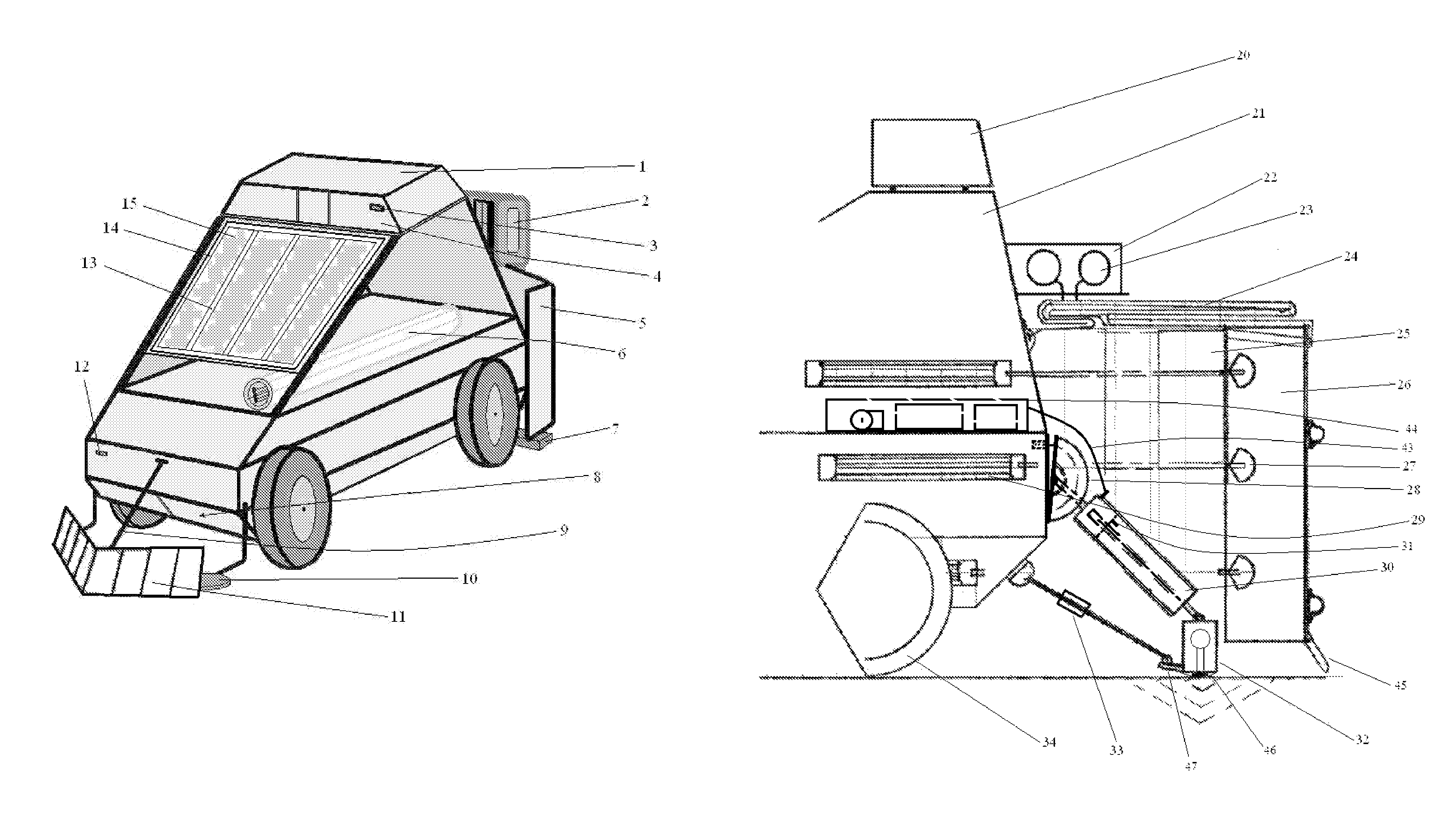
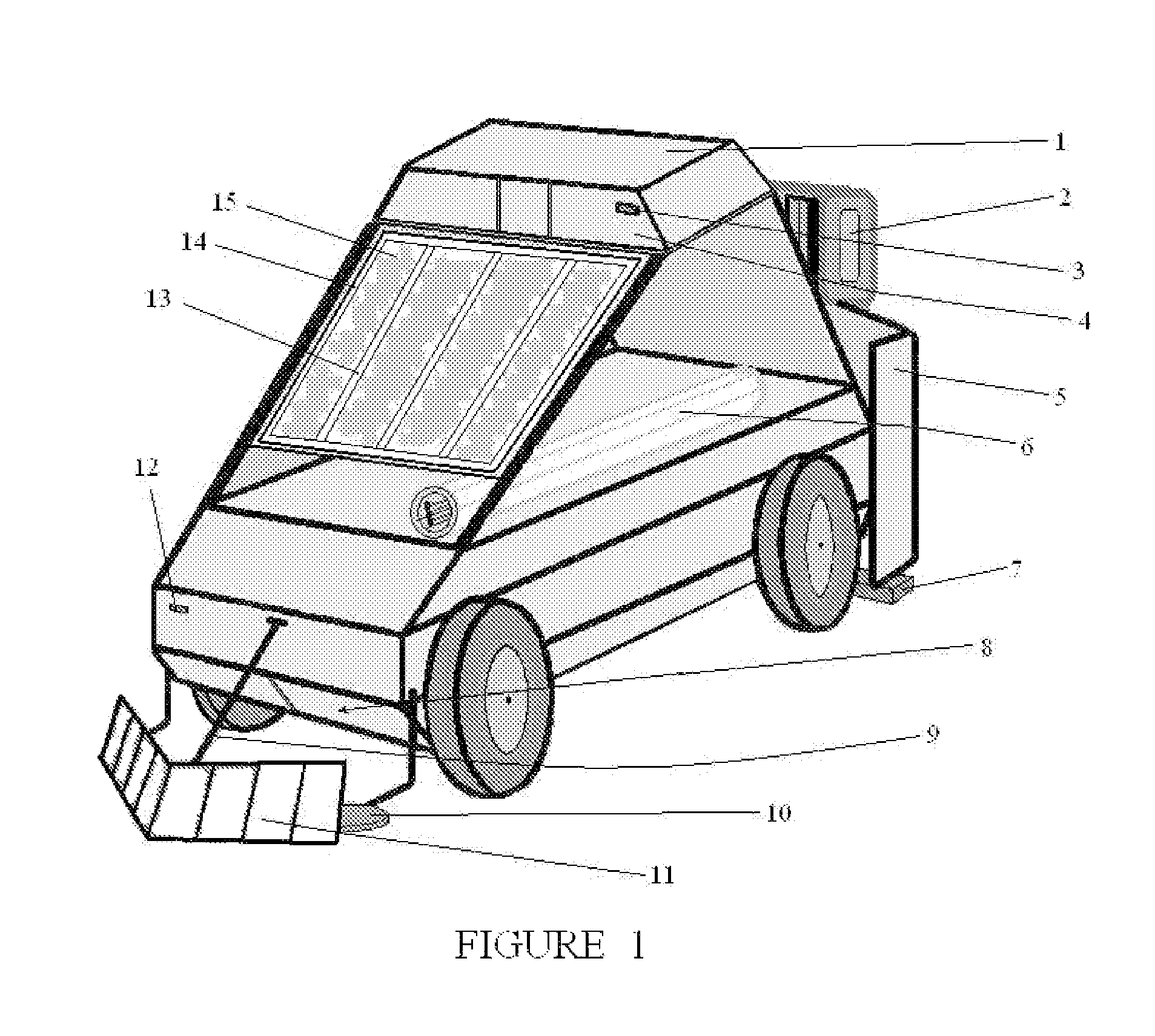
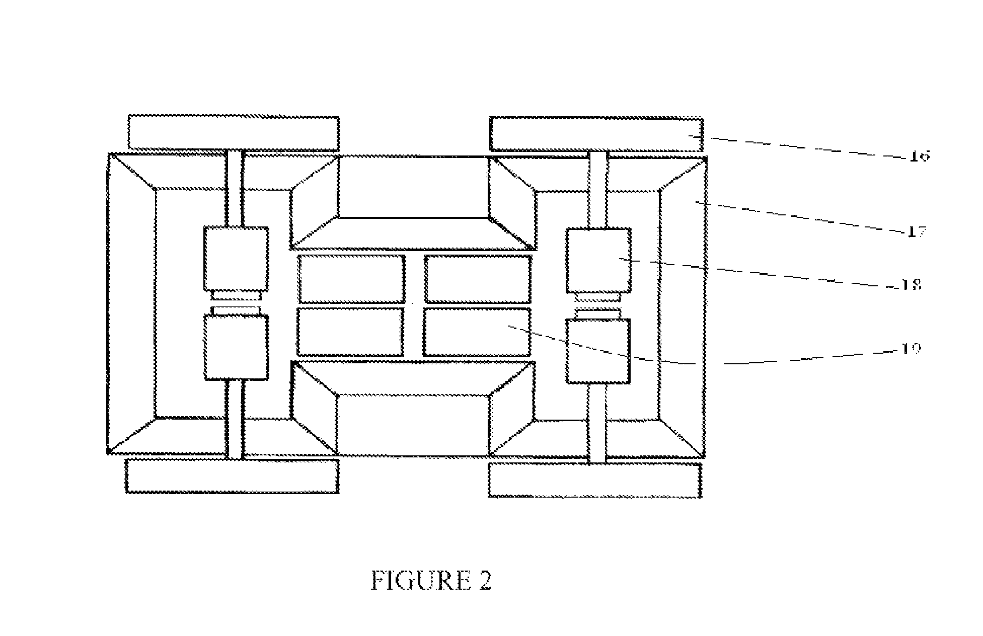
[0031]As shown in FIG. 1, is a new use non-conventional sized battery powered, solar charged, unmanned vehicle that is sized so as to create a clearing path for people travelling on foot. The first apparatus 11 is the self-leveling debris deflector. The primary chassis contains a solar panel 14 with a high resistant and magnification surface 13. From FIG. 2, a vertical interior section view looking down with the four drive wheels 16 can be found. Inside the chassis 17 are normal DC drive motors 18, current controller means and the battery set 19. The top of the chassis provides space for an optional bio-fuel power-plant that is not necessary but would provide added daily service hours that may be of advantage. In front of the chassis is an optical camera 12 for close in monitoring of operation of robotic arm that is stored in a recessed chamber 8 and for warning flag positioning. Above the chassis is a structural frame, which acts to support the photovoltaic cell module 14. This pan...


PUM


Abstract

A semi-continuous duty, Green Technology, self-charging 14, unmanned electric vehicle providing protection and security from underground mines. A deflector blade 11 follows natural existing contours to maintain straight line paths, while simultaneously carrying a mine detector 10, a vertical reciprocating ram set 30, 32 and 33 that preloads soil while also creating forward motion, followed by an energy dissipation and containment canopy system 22, 24, 26&29. The comprehensive system provides protection from mines on existing pathways in desert environments using a self-sufficient energy source. In addition, the total system utilizes only Green Technology for all modes of operation.

Description

[0001]This application is a Continuation-In-Part of application Ser. No. 13 / 184,505, filed Jul. 16, 2011 now U.S. Pat. No. 8,240,239.BACKGROUNDPrior Art[0002]The following is a tabulation of some prior art that presently appears relevant:[0003]U.S. PatentsPat. No.Kind CodeIssue DatePatentee7,493,974B12009 Feb. 24Boncodin5,856,6291999 Jan. 05Grosch et al.6,343,534B12002 Feb. 05Khanna et al.2,005,3921933 Apr. 18Remus4,589,3411986 May 20Clark4,519,5431985 May 28Szuminski6,216,7402001 Apr. 17Bunya[0004]This invention relates to a solar charging, battery powered, unmanned mine defeat vehicle. Current situations in specific geographic regions of the world have created a new need for defeating underground mines in desert-like terrain. This vehicle is especially to be used on existing paths in sand environments worldwide to protect against death and dismemberment, a long-time priority issue and establishes an effective tool for safe passage and security monitoring and creating secure zones....

Claims


Application Information

Patent Timeline
Patent Type & Authority Patents(United States)
IPC IPC(8): F41H11/16
CPCF41H7/005F41H11/28F41H11/13F41H11/18F42D5/045F41H7/042F41H11/16F41H5/007F41H5/06F41H5/20F41H11/00
Inventor DIAZ, KEVIN, MARK
Owner DIAZ KEVIN MARK
Why Eureka
Try Eureka