Self-locking cutting tool for plastic pipes

Inactive Publication Date: 2008-01-17
ROBERTSON DUANE D
View PDF8 Cites 4 Cited by
  • Summary
  • Abstract
  • Description
  • Claims
  • Application Information

AI Technical Summary

Benefits of technology

[0008]The locking mechanism for the cutting tool includes a bail member on the handle portion of one of the elongated members and a C-shaped catch member on the handle portion of the other elongated member. The bail member is pivotally mounted to the handle portion and can be manually moved to an out-of-the-way position while the tool is being used to make cuts. Upon completion of the cutting, the bail member can be manually pivoted to extend toward a surface on the opposing handle portion. As the handle portions are then squeezed together, the bail member abuts and slides along the surface of the other handle portion into engagement with the C-shaped catch member to secure the elongated members in a closed position. In the closed position, the knife blade is safely received in the anvil of the opposite jaw.

Problems solved by technology

Although simple and easy to operate, this locking arrangement has the disadvantage that the bail may be inadvertently struck and released as the tool is handled.
This can occur because the bail is on the outside of the handle ends exposing it to being contacted and released unintentionally.
If the tool is spring-biased toward its open position, the inadvertent release of the locking bail can then cause the tool to open, undesirably exposing the cutting blade of the tool.

Method used


Image

  • Self-locking cutting tool for plastic pipes
  • Self-locking cutting tool for plastic pipes
  • Self-locking cutting tool for plastic pipes

Examples


Embodiment Construction

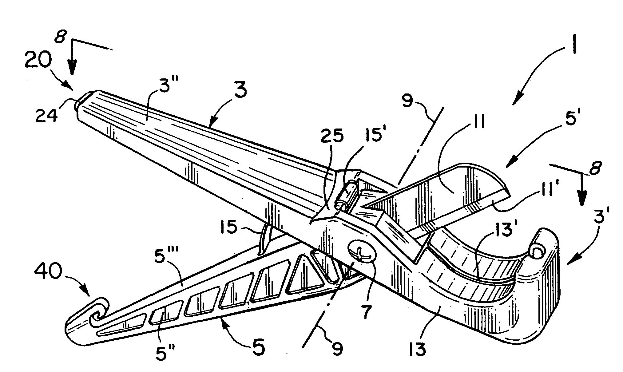
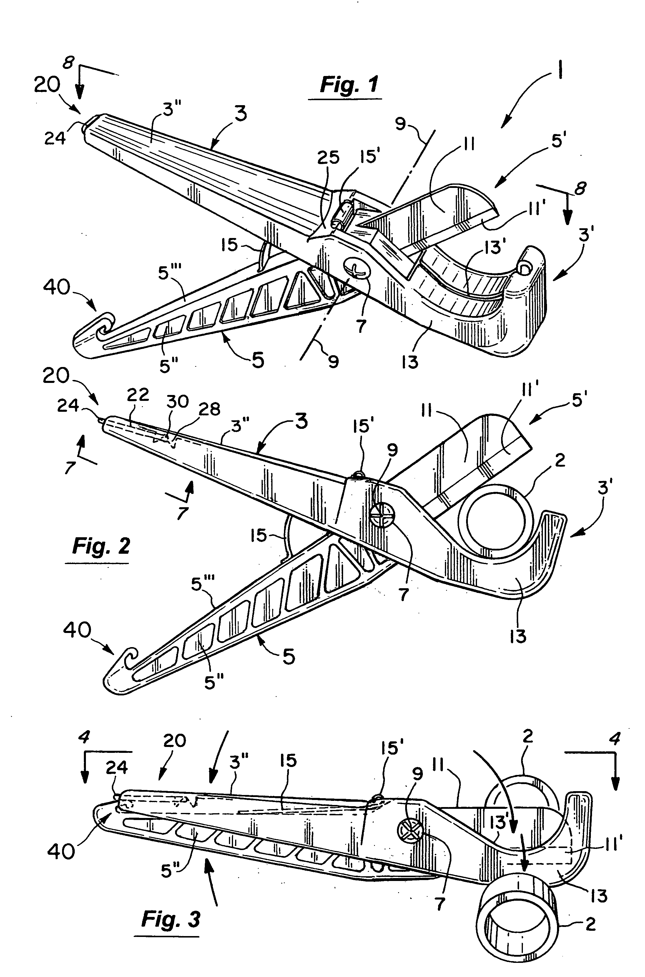
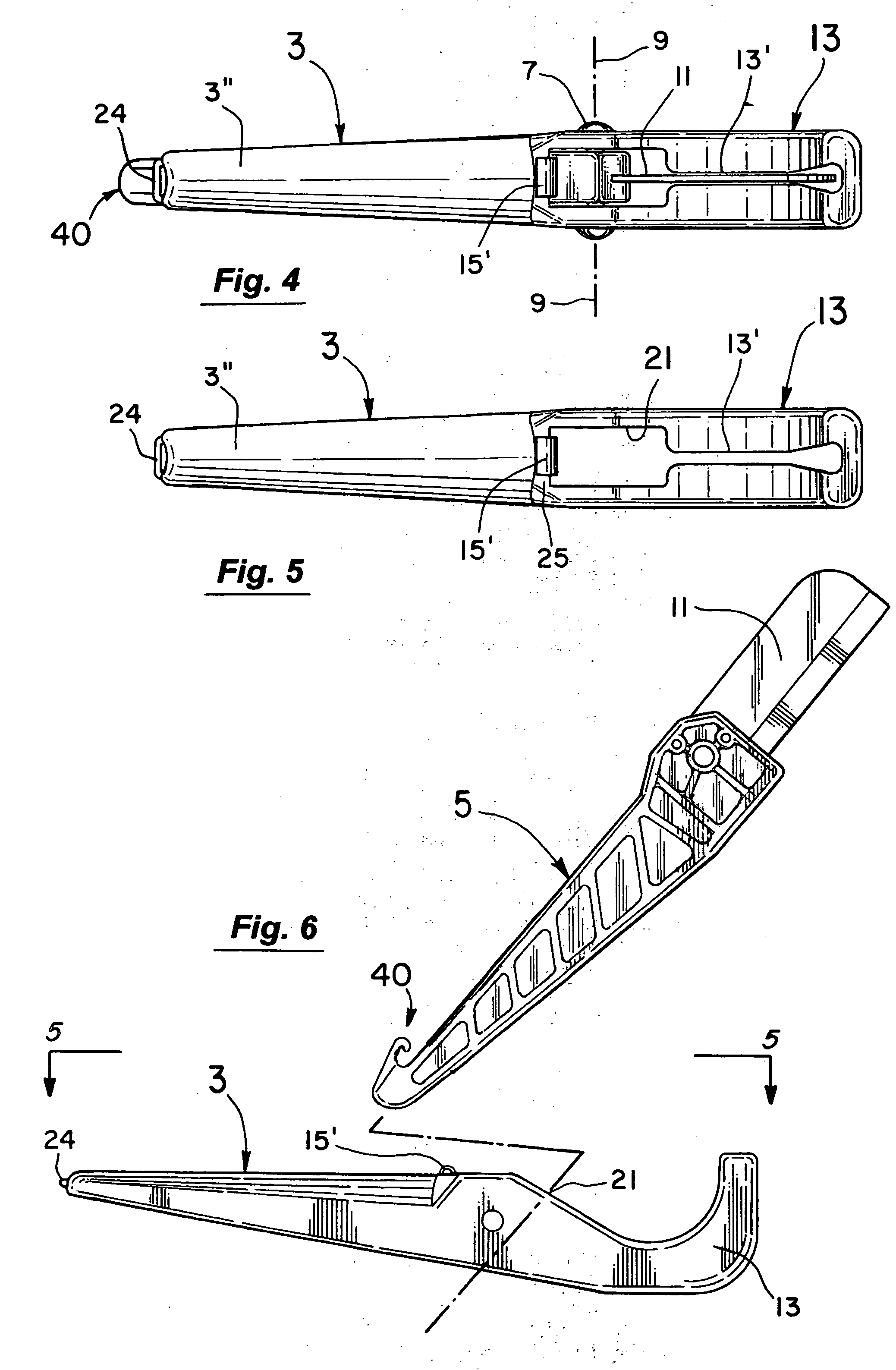
[0022]As shown in the perspective view of FIG. 1, the cutting tool 1 of the present invention includes two elongated members 3 and 5. The elongated members 3 and 5 are connected at 7 in a scissors-like manner for pivotal movement relative to each other about the axis 9. The axis 9 as shown is substantially intermediate the respective ends of the members 3 and 5. Each elongated member 3 and 5 has a jaw portion 3′ and 5′ and a handle portion 3″ and 5″. The jaw portion 5′ of the elongated member 5 (see also FIG. 2) has a knife blade 11 at one end thereof and the opposing jaw portion 3′ of the elongated member 3 has a curved anvil 13 at the end thereof.

[0023]In operation, the pipe 2 to be cut (see FIG. 2) is first received between the opened jaw portions 3′ and 5′. The handle portions 3″ and 5″ are then manually squeezed together as the cutting tool 1 is preferably swung relative to the pipe 2 until the pipe 2 is severed (see FIG. 3). In doing so as illustrated in FIG. 1-4, the cutting ...


PUM

PropertyMeasurementUnit
Angleaaaaaaaaaa
Angleaaaaaaaaaa

Abstract

A locking mechanism for a cutting tool for plastic pipes. The tool includes two elongated members pivotally connected to each other in a scissors-like manner. Each elongated member has a handle portion and a jaw portion with one jaw portion including a knife blade and the other an anvil. In the preferred embodiments, the jaws of the cutting tool are spring-biased apart toward an open position. The locking mechanism for the tool includes a bail member on one handle and a C-shaped catch member on the other. In operation, the bail member can be pivoted to an extended position to contact and automatically slide along the opposite handle into a locking position with the catch member as the handles are squeezed together.

Description

BACKGROUND OF THE INVENTION[0001]1. Field of the Invention[0002]This invention relates to the field of cutting tools for plastic pipes and more particularly to the field of manually operated cutting tools with locking mechanisms that hold the jaws of the tool safely closed when not in use.[0003]2. Discussion of the Background[0004]Cutting tools for plastic pipes are widely used throughout the world and are an essential piece of equipment for virtually anyone who works with plastic pipes. In a typical design, two elongated members are pivotally connected together in a scissors-like manner. In operation, the handles of the tool can be manually manipulated to separate them and open the jaws of the tool to receive the plastic pipe to be cut. In doing so, the handles can be rubbed along the user's leg to separate them and open the tool's jaws or the user can extend his or her fingers to separate the handles. Once opened with the pipe received between the jaws of the tool, the handles can...

Claims


Application Information

Patent Timeline
IPC IPC(8): B26B13/00
CPCB26D3/169B26D7/22B26D7/00
Inventor MORTENSEN, MARK A.
Owner ROBERTSON DUANE D
Why Eureka
Try Eureka