
Culture apparatus

Inactive Publication Date: 2008-03-06
KAMEDA SEIKA +1
View PDF8 Cites 17 Cited by
  • Summary
  • Abstract
  • Description
  • Claims
  • Application Information

AI Technical Summary

Benefits of technology

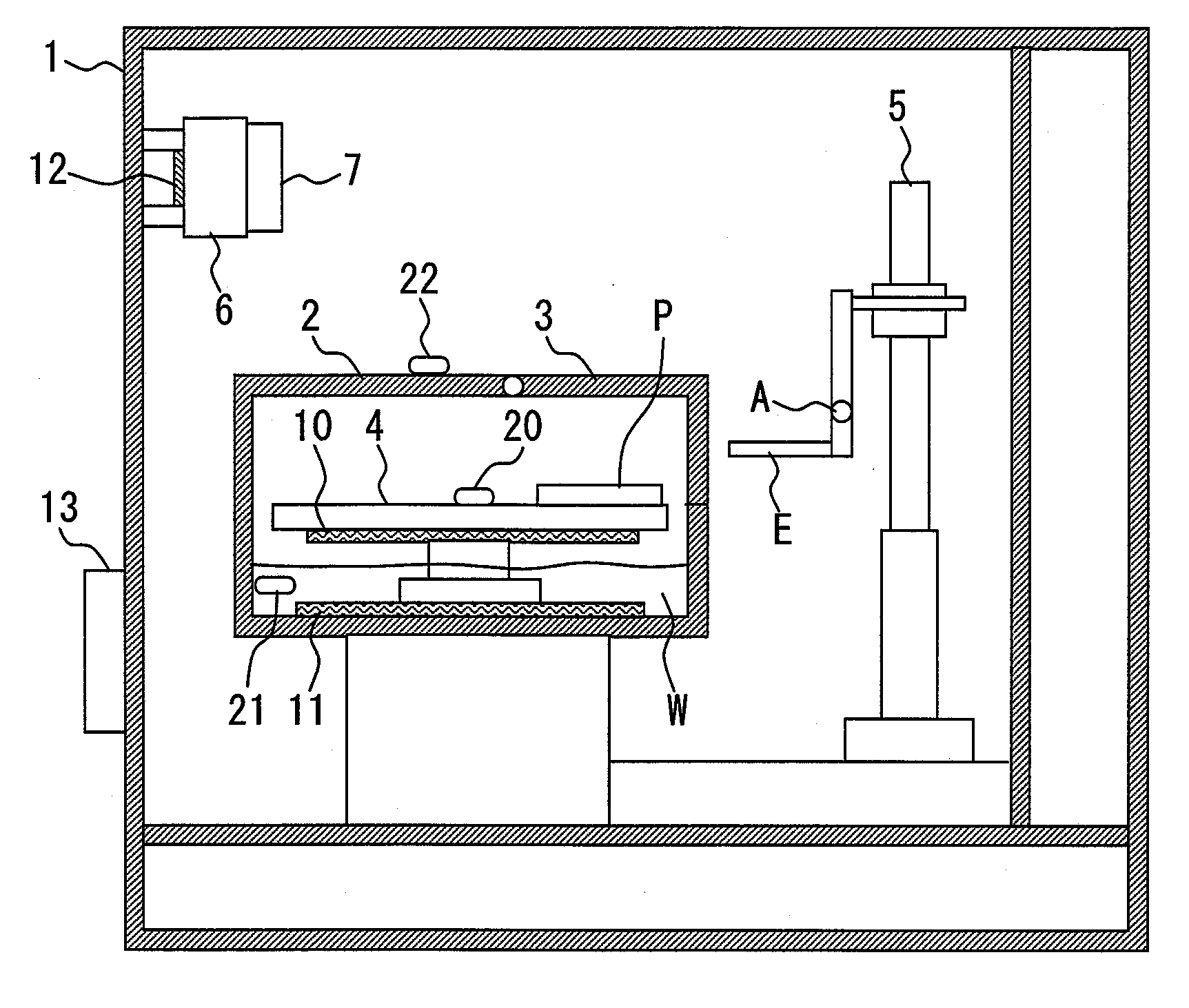
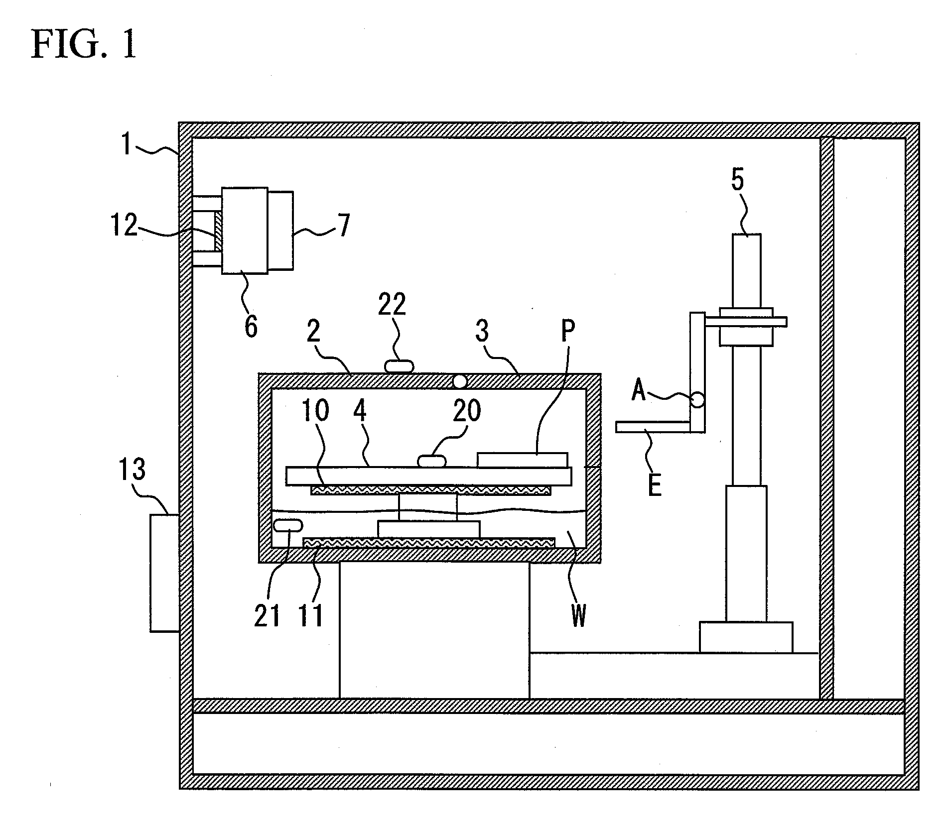
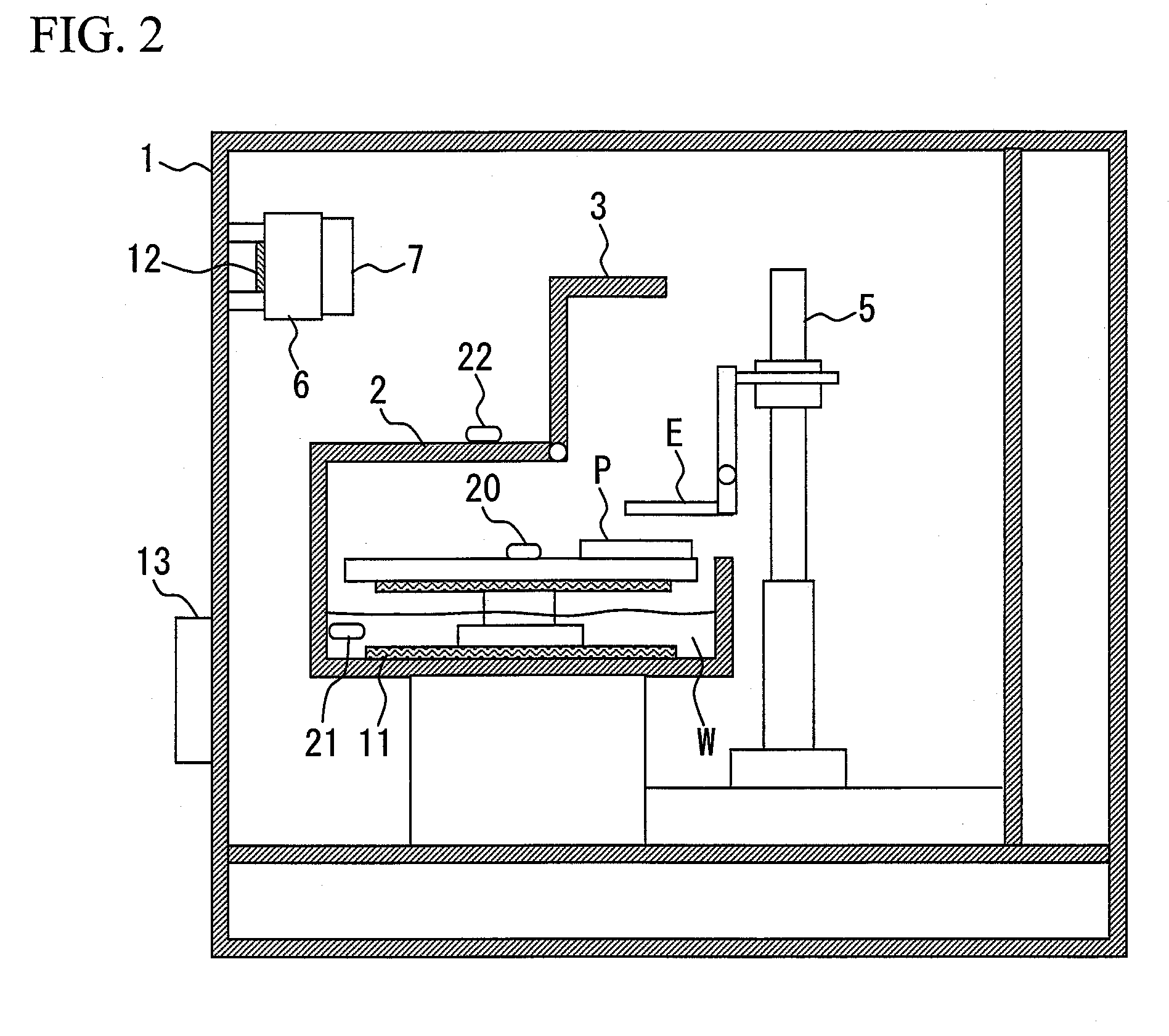
[0010]To solve the above problem, a culture apparatus according to the present invention is provided with a first chamber and a second chamber being a culture chamber, and a device for producing moisture is arranged only within the second chamber. Accordingly, a difference can be produced between the humidity environment of the first chamber and that of the second chamber, and thus a manipulator arranged outside the second chamber, accessible to the second chamber can be prevented from being adversely affected by moisture.
[0012]Also, a heater for heating culture vessels is arranged within the second chamber, allowing more stable maintenance of culture environment.
[0026]According to the inventive culture apparatus, preferable environment can be set for each element of a small culture chamber and manipulator, allowing an automatic culturing operation.

Problems solved by technology

However, in the culture apparatus disclosed in Patent Document 1, the through control of temperature and humidity environment has not been addressed.
Consequently, in the culture apparatus of Patent Document 1, mechanical devices having a movable part such as a motor, including the manipulator, are exposed to the environment of humidity of 100%, and thus dew condensation, resulting corrosions, and the like adversely affects the devices, which is not preferable.

Method used


Image

  • Culture apparatus
  • Culture apparatus
  • Culture apparatus

Examples


first embodiment

[0035]FIGS. 1 and 2 each illustrate a schematic configuration of an automatic culture apparatus according to a first embodiment of the present invention.

[0036]Referring to FIG. 1, within an automatic culture apparatus 1 being a first chamber, there are arranged: a culture chamber 2 being a second chamber constituting a closed space, having a door section 3; and a manipulator 5 for handling a small-sized culture vessel P and performing an operation such as replacement of culture medium. The outer wall of the automatic culture apparatus 1 is desirably composed of a heat-insulating material so that leaking of the internal heat is reduced to a minimum. Also, heat-insulating material, metal or the like can be used for the outer wall of the culture chamber 2. The use of a heat-insulating material for the outer wall has an advantage in that the internal heat of the culture chamber 2 hardly leaks and thus the internal temperature thereof can be controlled independently. The use of metal or ...

second embodiment

[0048]A second embodiment of the present invention will be described below with reference to FIGS. 3 to 5. FIG. 3 illustrates a schematic configuration of an automatic culture apparatus 1 according to the second embodiment of the present invention. In the automatic culture apparatus of FIG. 3, the configuration of a temperature maintaining device within the culture apparatus 1 is different from that of the first embodiment.

[0049]Referring to FIG. 3, gaps 9a, 9b and 9care arranged in walls of each chamber within the culture apparatus 1. In FIG. 3, a fan 7, filter 8 and heater 12 are arranged in the gap 9a; the fan 7 sends air to the heater 12. The heat production amount of the heater 12 is as with FIG. 1, controlled from the outside based on temperature information of the temperature sensor 22 arranged outside the culture chamber 2 so that a constant temperature is obtained. When this state is maintained, the air is circulated via the gaps 9b and 9cto reach gradually to a constant te...

third embodiment

[0052]An automatic culture apparatus according to a third embodiment of the present invention will be described with reference to FIGS. 6 to 7. FIG. 6 illustrates a configuration of an automatic culture apparatus 1 different from that of the first embodiment in the method of receiving the small-sized culture vessel P. Referring to FIG. 6, the culture chamber 2 is provided with multiple shelves receiving a plurality of small-sized culture vessels P, and respective shelves are provided with doors 3a, 3b and 3c independently openable and closable. Instead of being separately opened, these doors may be opened all at once, or may be constituted of a single door. However, when the doors are separately opened and closed, the opening area of the culture chamber 2 can be reduced and thus adverse effects of humidity on the manipulator 5 can be comparatively reduced.

[0053]Further, in order to stir the internal air to reduce unevenness of the internal humidity and at the same time to maintain t...


PUM


Abstract

The invention provides a culture apparatus capable of setting preferable environments for each element of a small-sized culture chamber and manipulator, allowing an automatic culturing operation. The culture apparatus according to the invention is provided with a first chamber and a second chamber being a culture chamber. A device for producing moisture is arranged only within the second chamber. Accordingly, a difference between the humidity environment of the first chamber and that of the second chamber can be produced, and thus a manipulator arranged outside the second chamber, accessible to the second chamber can be prevented from being adversely affected by moisture.

Description

CLAIM OF PRIORITY[0001]The present application claims priority from Japanese application JP 2006-238924 filed on Sep. 4, 2006, the content of which is hereby incorporated by reference into this application.BACKGROUND OF THE INVENTION[0002]1. Field of the Invention[0003]The present invention relates to a culture apparatus, and more particularly to a culture apparatus for tissue culturing (automatic culturing) of, for example, animal cells.[0004]2. Background Art[0005]In medical science- and medical care-related fields and the like, culturing of various types of cells separated from biologic bodies is being actively performed. In order to efficiently performing this type of cell culturing, the culture environment must be brought as close as possible to the environment within the biologic body in which this cell has resided before separation of the cell. Also, in the cell culturing, contamination must be prevented. Particularly, a human can be the largest contamination source, so the i...

Claims


Application Information

Patent Timeline
IPC IPC(8): C12M1/38C12M1/36C12M3/00
CPCC12M41/14C12M23/50
Inventor KAN, KAZUTOSHIKOBAYASHI, TOYOSHIGE
Owner KAMEDA SEIKA
Learn More